help_outline Skip to main content

6.3

Working on air valves
Art Love
Francis raised this and Chris and he decided that a new thread would be best. So I thought I would start one. The right front valve on the 300SE coupe had a significant leak which was dropping the right front corner very quickly. I had bought a set of second hand valves not long back. So I connected the compressor up the the right front unit using my specially made hose and shoved it in a bucket of water and it didn't leak. So I decided to swap valves. I did it today.

It is not an easy job on the car. We put the front of the car up on stands and removed the right front wheel. In the RHD cars, the steering box is in the road in front and above the valve. It would be easier in a LHD car. All sorts of bits and pieces are in the way and it is hard to get more then a fraction of a turn on a spanner on any of the air lines or the bolts. I used the two spanner technique which I described in the air bellows thread. I did not take any pictures today, but shall in the future.

The basic principles that I followed were as follows. Release the control rod at the ball joint. Release all the air lines with the unit attached to the axle. Use the pipe spanner to "crack" them loose, the an open ended 12mm spanner. You just can't get the pipe spanner on and off. I started with the one to the bellows in the middle on the bottom, then I did the ones at each end then the high level one at the top last. It is helpful to release the airlines where they are held to the subframe by the clamp. When all were fully released, and this involved a lot of time turning each one just a little at a time because of the very limited room. Then I released the two bolts that hold the unit to the subframe and removed the unit.

For instillation, I attached the inner line first. It has the least movement. It is absolutely essential to start every air line thread by hand. Cross threading is a disaster. To achieve this, I believe it is necessary to have the unit loose from the subframe so that you can move it in one hand while you try to engage the thread with the other. This more or less gets harder and harder the more lines are attached. I recall have dreadful trouble with the left front valve. Everything has to line up perfectly for the thread to start. Leave each one half done up till all of them are engaged. It is not a fun job. I then tightened up all the airlines and then installed the two mounting bolts. I found that I had to attach the inner of the two bolts first. With the outer one in, the inner one would not engage the thread. The other problem that I had that I had not forseen was that I left the mounting bolts out while I installed the air lines and then found that the I had dreadful trouble getting them in because the RHD steering box was in the way!

I finally got it all done, took the car down off the stands after putting the right from wheel back on and reattaching the control rod. And, guess what, the vavle leaked like a sieve from the center shaft, having shown no sign of a leak in the test!!! So the right front of the car went straight down again. Serves me right for not having the valve rebuilt before I put it on. So this is a job I shall be doing again in the near future and I'll take some pictures.

Art
Chris Johnson
Just out of curiousity, which port on the valve did you apply the compressed air for the test? I would like to think that this would be a valid test.

Chris Johnson
If you aren't constantly impressed with your car, then it needs fixing.
100.012-12-000790
100.012-12-000867
www.300SE.org
FEMA
Art, thanks for starting this thread; I'd like to address the approach to diagnosis as I feel intimated thus far by the air suspension system[:I]

I know Chris that you are intimate with this and at this point my plan is to look at a past service record in which my dealer tech dignosed which valves were leaking and need replacement. I'm also thinking perhaps I just replace all with new and be done rather than try to diagnose in the event I screw it up.

All that said it would be great to uunderstand how we should approach the problem to determine which valves leak and which don't because it's not like I have extra money to burn on unnecessary parts[;)]

This may already be outlined in a previuos thread and if so, I don't mean to add repeated information here but will go look over that thread and we can dialogue here and there as appropriate.

Francis E. Abate
Chris Johnson
I'll make a generalization, but it is accurate 95% of the time. If the car sinks after the engine is shut off, one or more height control valves is leaking.

These are no longer available new, so they must be rebuilt. I did recently pickup two "new" rear valves and two (one each side) "new" front valves. I haven't tested them yet, nor do I intent to because even so called new valves are still going to have to be rebuilt in order to be reliable after this period of time.

The most common leak in a late style valve (all 600s and 300SELs) is from the seal at the internal operating lever. This air usually leaves the valve assembly at the hinge pin for the external lever. Spraying some soapy solution (409, etc.) at this area on a valve that is pressurized will show bubbles if there is a leak. It is a good idea to spray the entire valve and connections with the soapy solution to reveal other possible external leaks. Other typical leaks are from between the line screw adaptors and the body of the valve and from between the line adaptors and the line nuts. Both of these external leaks are readily fixed with new rubber O-rings (of the correct type). Other than leaks around these fittings the valve is not repairable by us mere mortals, so they must be sent off for rebuilding.

I'll post some more later this evening.

Chris Johnson
If you aren't constantly impressed with your car, then it needs fixing.
100.012-12-000790
100.012-12-000867
www.300SE.org
FEMA
Chris;

I'm very disappointed these are no longer available new as I believed they were, but last I checked was a couple years ago now. The problem is I've heard the rebuilts don't have a good track record so if there are any sources better than others hopefully someone will post those here.

I'll look forward to your further explanation on leaks but suffice to say now my front end drops over time or when the car is not run often.

Francis E. Abate
Ron B
The rebuilt units are as good as the new ones in general. There are three main people world wide doing it. Neil Dubey being the first I believe to do it. if you want to spend a great deal of cash,the guy in Germany will fix them as new . In OZ we have Mr Black in Melbourne .
In all cases the rebuilt units will give as god a service as new ones and significantly cheaper. [:)]

quote:
12-14-2004, 11:49 PM #8
Tom Hanson
MBCA Member

What the heck, try to stuff a MB 6.9 liter V8 in it. What a machine that would be..
__________________
Tom Hanson
Orange County Section
Art Love
Chris,
It is a valid test. I'm with you on that. I was brain dead when I did it at the end of a long day at about 8pm and applied the air line to the E port instead of the B port. My bank balance is looking seriously empty at the moment and I was being too stingy to send a set of valves down to Alex Black in Melbourne for rebuilding. I'm just annoyed with myself because, as you know, changing one of these valves is not an easy job. The valve on the car was leaking air from the two screw holes that hold the high level pipe brass end fitting. I've not seen that before. There was no leak around the centre pivot bearing of the control lever or from the retaining pin hole. As far as I was concerned, it still meant that the seal on the centre toggle (operating lever) was leaking, letting pressure from the lower half of the valve into the non pressurized upper part. The one I put on leaks like a sieve from the control shaft pivot bearing - the usual place.

I'm getting too old to spend 3-4 hours on my back under one of these cars. I get quite nauseous for reasons I don't understand. Now I've brought the car home to put it on stands in my garage to get it out of Justin's shed because he needs the room. We have to take the radiator out to pull the oil driven fan coupling off and put new seals into it to stop the chronic oil leak from it as well as taking both front valves off to send down to Alex. Justin will send the valves from his 6.3 as well as a job lot. Today I went to start it from where I parked it on the road out the front of my house last night at the end of a long day only to have the starter motor totally die after as initial start. The damn thing is totally dead, so I've now got another problem to deal with even before I can get it into the garage.

Francis,
Tom Hanson confirmed that new valves were NLA when I asked him last year. New valves were still available when I rebuilt #1702 in the mid 1990's. I paid a fortune for them. They have lasted no longer than the rebuilt ones. Rubber seals are rubber seals. The big advantage as far as I am concerned is that Alex Black will be starting with valves that no one but Bosch have screwed around with. He told me that his biggest problem was dealing with trouble done by other people. I have had exactly the same experience when I was rebuilding my own valves. I had valves with Araldite, Sikaflex and all sorts of stuff in them - Loctite as well I suspect. Some of the valves I had would not unscrew - the brass end fittings sheared off before the valves moved. Most people mucking around with these things haven't got a clue as to how they work. I'll post the original Bosch cutaway diagrams here which include all the Bosch part numbers for the individual parts including the seals. I was still able to get the seals in the 1990's. I haven't tried since and still have some of them. I'm not posting the diagram for the part numbers so much but mainly to show you and others who are interested what is inside these units. It is appropriate for this thread.
Art
Art Love
Here is the diagram. The seal that leaks the most is 17 in the diagram.


It's getting a bit late and I don't want to start a long discussion on how this thing works at the moment. Chris may wish to go through it and I can add my tuppence worth if he does. Otherwise, have a good look at it and I'll go through it tomorrow. I'll also take some photos of some of the internal bits I have on the bench so you can compare them to the diagram.
Art
FEMA
I'll look forward to that Art.

Ron, I had heard even from Neil directly that the rebuilt valves are like a 50/50 chance of working or not so that is my concern - please correct me if I am wrong as it is not my intent to suggest poor work by anyone. It may just be that these things are tough to deal with.

That said does your guy in Australia or the guy in Germany give me the best chance of only doing this once? If you guys have their contact info please post it here and I will contact them directly and research price, availability, risk, etc.

Francis E. Abate
jeen
Hi guys

The site below is giving a good explination of the system

www.luftfederung.de

Jeen
Art Love
Chris Johnson will have the first part of his articles on the air suspension in the next Lode Star. That will supplement this thread, or perhaps it is the other way around[:D].
Art

P.S. I also was incorrect last night in saying that seal #17 in that diagram is the main cause of the leaks. It is a seal that is not separately identified on that diagram. Seal 17 surrounds a brass housing that looks like a black rectangle in the diagram in the middle of which is a ball with a vertical shaft through it. The seal that leaks is between the ball and the brass housing.
Chris Johnson
And it is that seal that cannot be replaced without damaging its housing, so a new housing is required. Just removing and re-installing this housing can damage the aluminum valve body if not done perfectly. This is one of the three principal reasons why repair of these valves must be left to an expert.

Art, I had to bail out on an important trip before I got time to finalize that article. I didn't think that it would make it into the next issue. Thanks to you and Anthony for picking up the ball and running with it.

Chris Johnson
If you aren't constantly impressed with your car, then it needs fixing.
100.012-12-000790
100.012-12-000867
www.300SE.org
Art Love
I promised to post some pictures of the bits and pieces.

Here is what you are used to. This is a left front valve, 2 A connections, 2 E connections, 1 B connection and 2 high level connections. That is 7 air lines and 2 bolts that you have to line up. I have spent over an hour or two or 4 connecting one of these valves up on a 6.3[:(].


If you undo the 2 screws that hold the high level unit to the top, and remove the unit it looks like this.


Then if you look into the cylindrical hole where it came from, it looks like this after you remove a teflon shuttle (and spring as I recall). I'll post a few pictures of the shuttle later.


The first thing is a teflon roller which is mounted on the shaft of the control rod. If you look at the diagram I posted, you will see that roller as a large striped disc. If you look carefully, you will note that there is a V notch cut into the circumference of the disc. It is at 7 o'clock in the diagram. Beyond the roller is the end of a steel shaft with a vertical steel pin located in a hole in the end of it. Beyond the shaft in the dark is a heavy spring unit.

Now, here is the teflon shuttle looked at from three perspectives.


upside down.


right way up.


and end on. The other end is circular with the bottom third cut away. You will notice on the upside down view, there is a V shaped ridge at one end. Well that ridge engages the notch in the roller on the control shaft when the roller is in just the right position to do so. When the ridge is engaged in the notch, it drives the shuttle one way or the other as the control shaft is pulled or pushed one way or the other. The pin you saw sticking out of the high level unit fits down that small hole in the end of the shuttle. At the other end, it fits over that steel shaft with the vertical steel pin in it.

If you undo the brass air line connections A and E at the opposite ends of the body of the unit, you are looking at the outer ends of the outlet and inlet valves respectively. Here is one of these valves.


I can't remember whether this is an inlet or an outlet valve. But if you push on the pin that sticks out of the inner end of the valve, you can quickly tell, because one has a soft spring holding it out and one has a very hard spring pushing it out. So, one is much easier to "open" than the other. To be quite honest, I've forgotten which is which, but I'm sure Chris will know. For the sake of what I am saying now, it doesn't matter. With the inlet and outlet valves out, you can look right through the cylindrical bore in the lower half of the valve unit.


What you can see, sticking down in the same bore that the airline connection B to the bellows screws into is the other end of the steel pin that you could see looking into the bore at the top of the valve unit. NOW I AM NOT SAYING THAT ANY OF YOU SHOULD DO ANY OF THIS DISASSEMBLY. This is for explanation only. I am sure that Chris and others will have their say, but there can be all sorts of problems doing this. The positions of the inlet and outlet valves in the bore of the unit are critical for example. When I have more time, I'll mention a few of the other problems I have encountered doing this.

This is what that vertical toggle pin unit looks like.


Here I am pushing the pin one way and the other to show you how it works. It is the seal INSIDE the brass casing, between the ball in the middle of the steel pin and the brass casing that causes 90% of the airleaks in these units. It does all the work.


You can see seal 17 in the diagram that seals the outside of the brass casing to the vertical central bore in the valve unit. The second circumferential cut out which is at the top of the brass housing (I'm holding it upside down in the two pictures) is to locate the unit in the bore using the steel pin that goes all the way through the casing. Here it is beautifully undisturbed in this unit. It is right in the middle of the picture.


Here is what you need to drive it out to release the center toggle unit.


Don't ask how many of these fine punches I have broken trying to drive out these pins.[B)] They have a very slight taper and I could never remember which way they drove out. Electrolysis often siezes them in as well. I got this one out.


So, leaving it at this stage, because I have to go out, when the suspension drives the control rod up or down, it rotates that roller which moves the shuttle one way or the other and the shuttle pushes the top end of the toggle pin in and the heavy spring pushes it out and at the opposite (lower) end of the toggle pin, the ball on the end either pushes the inlet valve open or the outlet valve open accordingly. In the central position both are closed. I'll do some more tomorrow when I have time.
Art
paul-NL
Watch out !!!


Those "bullet"valves are DIFFERENT for the inlet- and outletside and don't switch them.

What is the difference ??
The spring from the = as I remember well = outletvalve is MUCH STRONGER then the spring from the inletvalve.
Chris Johnson
Indeed, the one with the strong spring is the outlet valve. The inlet valve has a check valve in it to prevent the reverse flow of air, and this allows a very light spring to be used to hold the flow valve on its seat. Because of the check valve, it does not matter if the flow valve is blown off its seat when the air bag compresses and the pressure at the "B" connection goes above the pressure behind the flow valve.

The outlet valve, on the other hand, does not (and can not) have a check valve in it, so the flow valve itself has to be able to withstand normal pressures as well as these transient over-pressure situations and not allow any air to escape, and it is that big spring that ensures this. The valve must open only when it is physically opened by the lever.

Chris Johnson
If you aren't constantly impressed with your car, then it needs fixing.
100.012-12-000790
100.012-12-000867
www.300SE.org
Ron B
The guy in Germmany makes his own toggle valves and I think he sells them to those who want to repair their own valves. Once the amount of effort required to make such a part to high degree of precision is recognized then it will be understood why the overhual cost is so high. [:)]

quote:
12-14-2004, 11:49 PM #8
Tom Hanson
MBCA Member

What the heck, try to stuff a MB 6.9 liter V8 in it. What a machine that would be..
__________________
Tom Hanson
Orange County Section
Art Love
You don't have to get them from Germany. Geoff Summers, an aeronautical engineer at the Gold Coast has had a lot of the brass housings reproduced. The steel levers don't wear out and are reusable. The problem I had with Geoff's units when I visited him back in 1995 was that he was using a round profile O ring rather than a square profile one in his toggle rebuilds. The square profile ones fail soon enough. I have no experience with any of Geoff's rebuilt valves, so my objection was theoretical rather than based on any hard core evidence. I know Geoff is still rebuilding valves 15 years later, so maybe I was wrong. In fact he has done 2 of the 3 valves I am going to use on my LWB Finnie sedan (he could not get the third one apart), but they are a totally different design.

I also believe that Neil Dubey has had new brass housing made if my memory is correct. The housings have to be swaged around the rod at their lower end once the new seal is inserted as Chris has already alluded to.

I was still able to buy new toggle units from Bosch in 1995 as well as seals. Here is a picture of some of the packets and a copy of the old faded invoice. You probably can't read any of it, but it is dated 29th June 1995 and it is for seals and two toggle units which cost me A$145 each back then, 15 years ago


Unless someone has some questions, I shall leave my discussion on how the valves work at this stage. Chris will cover it as well in his Lode Star articles better than me. What I did want to talk about a little was all the sorts of trouble I have had trying to rebuild these valves. I have already said the Geoff Summers could not get one of the early version valves apart. This was because someone had glued/Loctited it together. People who have not got a clue as to how these valves work and who don't want to spend money having them repaired properly do all sorts of dreadful things. Alex Black also told me that his biggest problem in repairing valves was trying to deal with damage caused by other people. I recall that when I visited Geoff Summers back in 1995, he had a pile of aluminium housings 3 feet tall against the wall at the end of his room. Neil Dubey had the same thing. Alex is running out of good housings.

So, I believe that we should all save the housings that we have and not do dreadful things to them, but send them to good people who repair them properly, several of whom have been mentioned here and elsewhere on this Forum. Here is a list of some of the problems I have personally had.

Unable to remove the inlet and outlet valves from their threads because of glue, Loctite, etc. The end of the valve has a small square recess in it. This recess is the only thing that you can use to unscrew it. The end is fine brass. I cut down a small flat screw driver to fit the recess perfectly and still got nowhere on more than one occasion. The brass broke before the valve moved.

As already said, unable to drive the steel locking pin out of the aluminium housing - end of story.

Unable to move the toggle unit up to release the small bottom shuttle between the pins of the inlet and outlet valves.

Having pushed the toggle unit up to release it at the bottom, being unable to get it back down. I have one sitting on the bench in an otherwise good body where the top lip of the brass housing just refused to come down into the bore - end of another story. You need special tools. I modified a pair of needle nose pliers to grab the lower ball on the toggle shaft, but there were still times that I could not move it.

Locating the toggle shaft at the top against the strong spring is tedious.

I have no way of rebuilding the inlet our outlet valves which I am told contain 13 individual bits/seals. I've never pulled one apart to find out. Ditto the high setting unit.

So, I am quite happy to pay someone who knows what he is doing $350 a valve to repair them, both from a time and cost point of view, and certainly from a piece of mind point of view.

I think it is interesting to have had a crack at it in 1995 and to have managed to rebuild valves that have done 10 years of service, but I don't want to do it again and I don't think people new to these cars, unless they have special skills and tools, should try to reinvent the wheel.

Questions and comments cheerfully accepted.
Art
wbrian63
Art / Chris

I have a question about how the valves handle transient inputs. If this is to be covered in Chris' upcoming article, I'll wait until then.

Specifically, what I'm talking about is what is used to delay the actual inputs to the valves from the levers actually causing air to be injected or released from the bellows? I would think one wouldn't want there to be a constant process of injection / releasing as the car bounces up and down the road during normal travel.

As an aside, I read with interest how the valves are designed differently to deal with the inlet and exhaust pressures present in the valve body. Years ago, while rebuilding a level control valve for my now-gone '66 Cadillac Fleetwood, I was amazed at the technology implemented to provide a mechanical control of air into and out of the air shocks. To be sure, this was not a full air suspension, but rather an air-assisted suspension, and only in the rear. However, the issues were the same - how to vent air when required to lower the car, and how to add air when needed to raise the car and keep it in the system, and also how to prevent constant +- activity while in motion. Cadillac's solution involved 2 Schrader valves - the type used in tire valve stems. On the inlet side, the valve was mounted with the actuating stem towards the inside of the valve - seal towards the pump. Since the pressure on the pump side was always higher than the pressure in the system, that kept the valve closed. When air was needed, the stem was depressed, allowing air to flow into the system. The exhaust side of the valve was a bit more ingenious. It used a modified valve, with a stem attached to the seal side of the valve - the stem had a head on the end. The natural pressure in the system (along with the spring inside the valve) kept the valve closed. When air needed to be vented, the stem was pulled, opening the valve and releasing the air.

The actuation of the valves was handled by a lever - one end resting on the inlet valve, the other, with a notch to slide over the valve-side stem of the exhaust valve, under the aforementioned head. The lever was connected through a viscous damper to the outside of the valve where another lever was attached to one of the cross-link members that supported the top of the rear axle. Movement of the arm on the outside resulted in movement on the inside, but because of the damper, only in a delayed fashion. Additionally, because there was no mechanical connection from the outside arm to the inside lever, large movements of the arm still only produced the small (about 3/16" either way) movements of the lever.

Air for the system was provided by a diaphragm pump that ran off engine vacuum. It had a reservoir tank of perhaps 1.5 quarts volume attached to it. The diaphragm was about 5 inches in diameter and they acted upon a piston about 1/4" in diameter. Stroke was perhaps 1/4 inch. 14" of vacuum was more than enough to produce amazingly high pressures in the tank - albeit very slowly. I attached a 200psi gauge to the test port of the tank and the gauge was pegged most of the time... A fully exhausted tank took about 10 minutes to fully pressurize at idle. There was a regulator on the tank to limit the air going to the shocks to about 125psi - the limit of those devices. The air inlet to the pump was off a hose that attached to the air cleaner, inside the perimeter of the air filter. Unfortnately, there was no drier fitted to this system, so most of the reservoirs failed due to rust.

Sorry to divert the thread...

Regards

W. Brian Fogarty

'02 S55 AMG (W220)
'92 300SE (W140) - sold
'76 450SEL 6.9 Euro #1164 - parted & gone
'76 450SEL 6.9 Euro #521

"Bond reflected that good Americans were fine people, and most of them seemed to come from Texas..." Casino Royale, Chapter VII
Chris Johnson
Hello Brian,

This system does operate with potentially constant inletting and exhausting of air. On a rough road, the system will be very busy.

This is a large part of the reason why the system uses a constantly operating, high reliability air compressor and has a relatively large air storage tank. The system has a number of throttles, in the form of small diameter bores, to slow down the transfer of air though.

There is some small amount of "dead play" in the height control valves, but this is frequently misunderstood to be to furthur mitigate the amount of air flow in the system. This is not true, and the amount of dead-play is generally set to a much greater value than is actually needed, or desirable.

Note that this system is truly an extremely reliable system, with failures occuring in the rubber seals, not the mechanical parts.

Chris Johnson
If you aren't constantly impressed with your car, then it needs fixing.
100.012-12-000790
100.012-12-000867
www.300SE.org
jeen
http://w-100.de/cms/index.php?option=com_content&task=view&id=9&Itemid=23

It seems like this company selling the single parts.

Jeen
styria
What a fascinating subject this is, and the many headaches it seems to create. For anyone interested, I can supply fully rebuilt valves for the later 109 models at a price of $380.00 each on exchange, plus postage. They are fully warranted for a period of twelve months.

For oversead customers, i.e. US and Europe, there is a core charge of $A 200.00 or, preferably, if you send your old valve first for examination to suitable reconditioning, there would be no core charge. But the valve taken in exchange should not have been interferred with in any way.

I read Art's post with a great deal of interest. I have just fitted two front valves, but waht my work somewhat more difficult, was the fact that all the fixed steel pipes had been removed as well. So really I started off from scratch and just fitting the steel pipes temselves that connect the two valves is frustrating, as well as time consuming. As Art says, you must not cross thread any of the fittings.

You can also contact me on my webpage, namely 'topklasse.net.au' - some M100 members are already contributors to the site. Regards Styria

"My Gleaming Beauty"
Art Love
I've been removing the three axle valves from the W112 300SE coupe to send them away for rebuilding. The rear stays up, but I'm sending it anyway. So I took the oportunity to use my little Kodak camera to take some shots as I went along in the hope it will be useful to someone. The car is back home here, so it is on stands, not the comfort of the hoist at Justin's. We also have a jack under the front subframe to give it and the motor a bit of support while the stands hold the body.

The left front valve is the worst to get off and worse still to get back on. The W112 is easier by far for this valve than the 6.3 which has steel pipes to all 7 connections. The time to do the 6.3 valves is when the front subframe is out of the car for any reason. It is a dog of a job on the car.

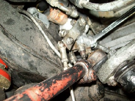
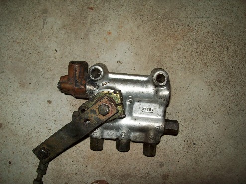
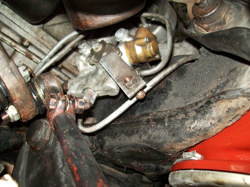
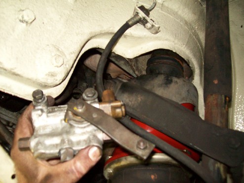
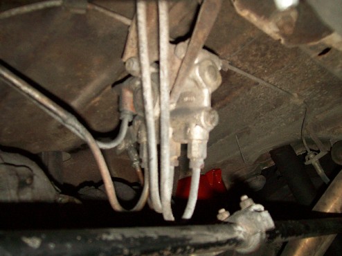
Further down is a picture of the left front valve after I removed it. It has two high level connections to the brass part. It has an end inflow connection on the left and a lower inflow connection on the bottom side at the left. In the middle on the bottom is the connection for the left front air bellows. On the right are the two outflow connections, one at the end and one at the bottom. In contrast to the 6.3, in the 300, three of the connections have hoses attached rather than steel pipes making life easier. The two end fittings and one of the high level fittings have the hoses.

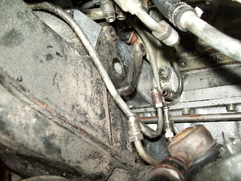
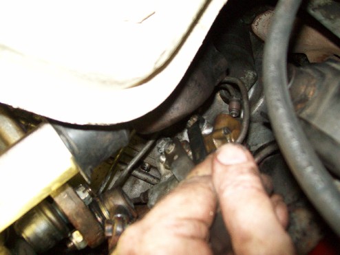
I undid the end E fitting first. You can see the threaded fitting in the middle of the picture at the top. The hose allows the end to move a long way out of the way. I then undid the three bottom fittings, doing the E nearest the camera first, then the B in the middle and then the A last. At the time I took the picture, I had just started on the far A fitting with my 14mm open end spanner on the brass attachment on the valve and the pipe spanner (flare nut wrench) on the pipe fitting. Squeezing the two spanners together cracks the thread. Then you have to use an open ended 12mm spanner to undo the rest.


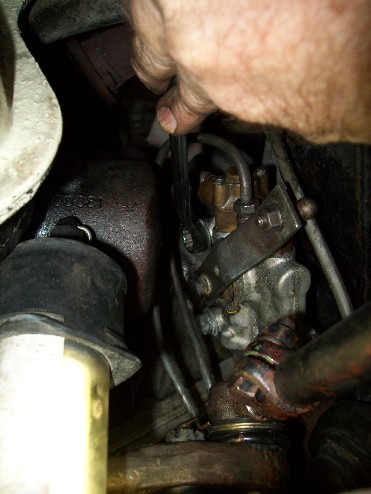
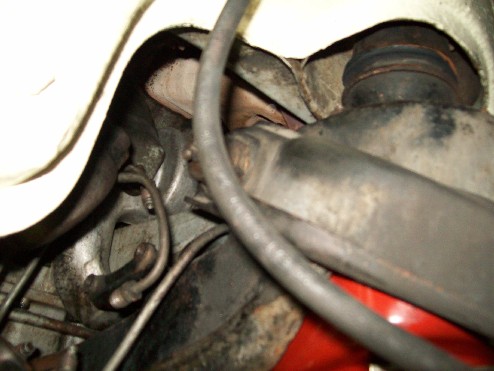
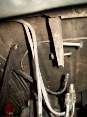
This is RHD but you can see how the steering mechanism is in the road. I've undone the two high level lines as well. You can't use the two spanner technique on them, because there is nowhere for the 14mm spanner to go. There is not much room up there. You can see it better in the pictures I took on the other side. You can see that I still have the ball joint for the control rod intact. That was not deliberate, it just happened that the lower ball on the lower control arm let go before the one on the valve arm.

This picture is a bit fuzzy but it shows the bottom E,B and A pipes undone across the bottom of the valve unit.


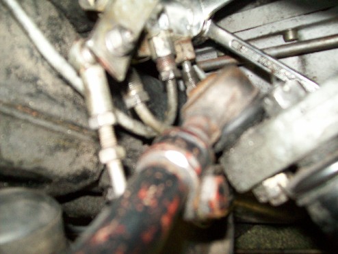
This is similar from a bit further back.


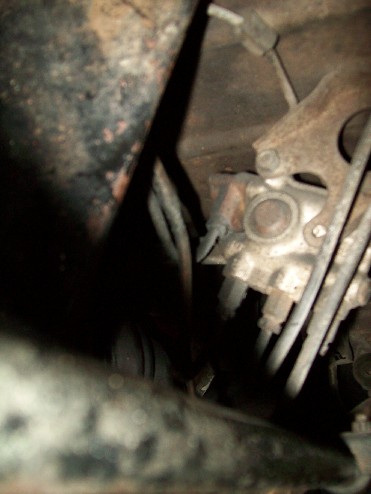
I shoved the camera up behind the steering damper to take this. I didn't see it from this perspective myself. Note the in the past, someone has had trouble with the nut on the A fitting rounding off and has filed it down to a square 10mm.


You can also see that I have the valve retaining bolts loose and in fact, the right one is out. A 13mm long socket spanner did the job for them on this side as there was plenty of room.

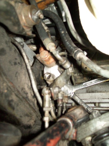
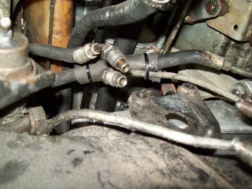
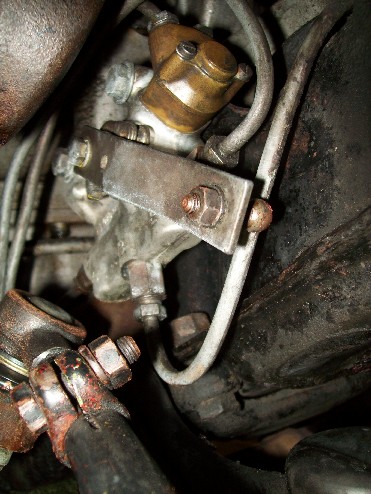
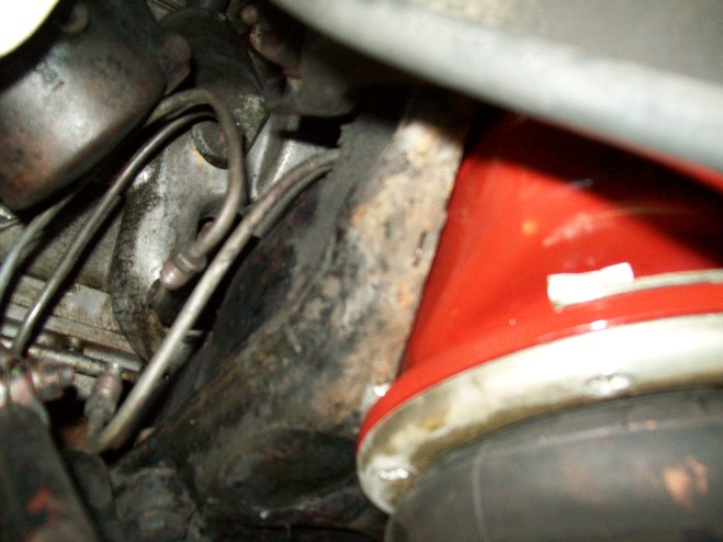
And, after all that and the nice pictures of the two spanners, the pipe spanner just rotated on the far A fitting, so I gave up last night when I did that job and started again this morning with the vice grips to release that fitting, again with the 14mm open ender on the valve end. So that will be another thing to fix before the unit goes back in. Here is a picture showing where it came from. At the top you can see the two high level lines above and in front of the end E hose fitting. The three lower pipes are obvious with the B line sticking up more than the other two. At the far end you can see the A hose end fitting. In the middle is the bracket with the two welded nuts at the top.


This gives a good view of the two high level pipes (the inflow one from the master valve is a hose). That's the B line tracking up to pass inside the trunion where it should be protected by two thick rubber hose spacers.


The set up is the same on the 6.3, you just don't have the luxury of the rubber hoses. Here is another general view.


And it is out[:)]


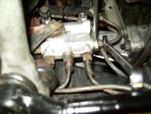
Now the right side. This should be pretty straight forward on LHD cars. On this car, the steering box and arm are in the way. There are three less lines, one high level and the bottom A and E lines. You can again see the B line tracking up behind the subframe to go across the top to the bellows, missing its rubber protective hose. I've bought a metre of the hose to fix this up as well as to use on Justin's and other projects.


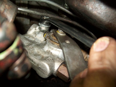
Here is a close up. I've got the control rod off the correct end this side. That's the front of the power steering box and steering arm protruding in from behind. No room for a socket here. You can see that I have got the B line started. If it won't undo with fingers, it is tedious, because there is only enough room for a part turn of the 12mm spanner which has to be repeatedly reversed. This applies a lot doing this. The E line just above the control arm is straight forward on this side.


I've cracked the high level line with the pipe spanner and have managed to get my hand up in there to undo this line with my fingers.


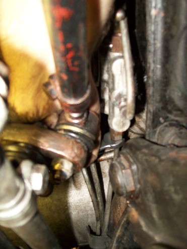
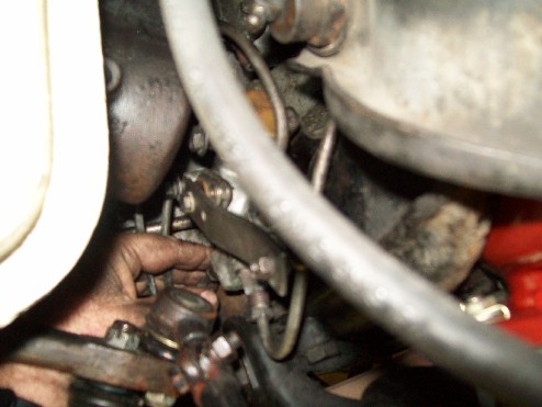
Now I'm working on the A fitting at the far end. That funny looking yellow thing is the palm of my hand squeezed in above the steering arm in front of the power steering box with my trusty 12mm spanner. I've already done the two spanner trick to crack it. You will notice that the rubber spacer is missing from the bracket holding the three lines to the back of the subframe in the distance. That is another job for me. If it were there, I would loosen it anyway while working on this line, particularly when reinstalling this valve.


I've decided to release the unit before I finish undoing the A line because I can't get it free enough to use my fingers, and there is no room to swing the spanner. So now I am undoing the two bolts, outer one first. With the power steering in the road, I cannot fit a socket and am using a closed 13mm spanner. You can see the end of the released high level line above the end of my thumb.


Here is another view of the same thing.


Now I'm onto the inner bolt. I remembered when I changed this valve recently that the bolts had to go into the unit before the unit went into place, because with the unit in place, there was insuffient room to get the bolt into its hole because the power steering box was in the way. I don't know if that is the case on the left in LHD cars, but it is worth bearing in mind.


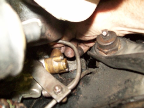
Now with the unit free, I can get my hand in to undo that A fitting with my fingers. That's the brake line ruining the picture. There really is not much room[:(].


And it's out[:)].


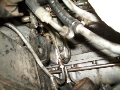
Couple of shots of where it came from.


Now the rear one.


This is very accessable with the exception of a problem I recall having before. That is getting the high level fitting undone. The two spanner trick works easilly here on the A,B and E lines. As at the front, there is nothing on the valve unit for the 14mm spanner and I found there was only one way I could apply the pipe spanner (flare nut wrench I think you call it) and that was in the most mechanically disadvantagous position for my hand. You have to undo the fittings before you undo the two bolts, and at the rear, the nuts are not welded, so you need a 13mm socket and a 13mm spanner.


When the units come back, I'll complete this thread with some words and pictures on reinstallation. Hope it is all helpful for someone.
Art
werminghausen
I offered to share my limited experience on air valves.
For the story: I have bought a 'sinking' 300SEL and was reading about the valves and decided to take them apart because I am just interested if they are repairable.
I took the 3 valves completely apart and was machining 'sleeves' for the 3 valves stk, e and a.
before taking the valves apart I was analyzing them. I built a test stand and did pressure tests in order to figure out what the problems are. I found stk faulty in all cases and also the e valve is suspect. a valve was good in all cases.
I wanted to figure out what the tolerances were in operation. I mean when the car is standing and I press it down by my weight at what tolerance does the valve start adjusting: some people said 1cm but have no reliable source. 1 cm could be translated into an angle difference of the main lever on the leveling valve. I expect the angle difference less than 1 degree before the stk valve will operate the e or a valve?
I am collaborating with a friend in Germany (he is working for Bosch in Stuttgart) who has access to a tiny lathe because the valve bodies are so tiny and relatively precise that a regular lathe can't be used. Also the tools for machining the parts need to be special. So i understand today why remanufacturing these valves is expensive and why there are some mystical tales around these valves.
Right now I have machined all new valve bodies according the old bodies which need to be destroyed if you want to harvest the inner parts. Precisely the flanging of the parts is the reason they need to be destroyed.
stk is the most challenging part of the 3 and the main cause for our sinking cars. I changed the design of the custom Bosch o-ring, therfore changed the original design in detail at the ball seat to a standard seal ring and did tests. The first pressure tests at 10 bars were sucessful.
If you are interested I can tell you more. Martin
Ron B
yes please![:)]

quote:
12-14-2004, 11:49 PM #8
Tom Hanson
MBCA Member

What the heck, try to stuff a MB 6.9 liter V8 in it. What a machine that would be..
__________________
Tom Hanson
Orange County Section
Art Love
Keep going Martin.
Art
werminghausen

My questions to the knowledgeable people here is: When I assemble stk, e and a valves into the valve body back- what are the correct adjustments. What 'play' has the toggle before it activates a or e?
I would appreciate your comments here. Martin
Art Love
Martin,
I'll have to undo the B fitting on one of my spare valves to answer that. Not sure when that will be, but I will do it for you.
Art
werminghausen
quote:
Originally posted by Art Love

Martin,
I'll have to undo the B fitting on one of my spare valves to answer that. Not sure when that will be, but I will do it for you.
Art


Thanks Art
My 2 questions are:
1) What is the set angle for the exterior lever for Neutral (no activation for e or a .
My guess this angle is 15 degrees (+ 1 degree according my analysis) down from the horizontal. Please confirm.
2) What is the tolerance of lever movement when e and a valve are activated? The tolerance is +/- 2.5 degrees according my analysis of the 3 valves I took apart.
I heard Michael Brockhoff saying that the air valves are adjusting at a height difference of 1cm! I need to get these 2 questions confirmed before I put the valves back together.
Any help here is good. Martin
Art Love
15 degrees seems correct to me. I had trouble working out the other measurements. It is hard to tell when the valves open and close without an air feed and with the shuttle in place, I can't see when the toggle engages the A and E valve pins via the B port. By feel, what you say seems close, but I had no way of measuring it. In reality, the sensitivity of the lever is dependent on how far in the A and E valves are screwed. I don't know and never did know whether they are screwed in to the limit of the thread in the valve body, or whether there is a set position. The other problem I have had is that with the exception of the two front valves on #1702 which I bought new, I have no way of knowing whether the settings on the valves I have are factory.

Almost invariably, someone has pulled them apart at some time in the past trying ignorantly to fix the air leak that is usually due to failure of the centre seal in the pivot. When I pulled a spare valve apart yesterday to see if I could answer your questions, I found a cast of the valve body bore in silicone sealant in the A valve housing[:0]. At least the valves had not been Loctited in as I have found in the past and unscrewed without damage. Hopefully your friend at Bosch can access this information for you.
Art
werminghausen
quote:
Originally posted by Art Love

15 degrees seems correct to me. I had trouble working out the other measurements. It is hard to tell when the valves open and close without an air feed and with the shuttle in place, I can't see when the toggle engages the A and E valve pins via the B port. By feel, what you say seems close, but I had no way of measuring it. In reality, the sensitivity of the lever is dependent on how far in the A and E valves are screwed. I don't know and never did know whether they are screwed in to the limit of the thread in the valve body, or whether there is a set position. The other problem I have had is that with the exception of the two front valves on #1702 which I bought new, I have no way of knowing whether the settings on the valves I have are factory.

Almost invariably, someone has pulled them apart at some time in the past trying ignorantly to fix the air leak that is usually due to failure of the centre seal in the pivot. When I pulled a spare valve apart yesterday to see if I could answer your questions, I found a cast of the valve body bore in silicone sealant in the A valve housing[:0]. At least the valves had not been Loctited in as I have found in the past and unscrewed without damage. Hopefully your friend at Bosch can access this information for you.
Art


Hi Art,
as I mentioned before I have built a test stand in order to test the operation of 3 old valves. I built a jig for in order to know at what angle the lever is during testing, then I connected the E /A /Stk with a special fitting in order to apply air pressure. For air pressure and measuring pressure I was using my A/C gauge set.
The setting I described (15 degrees +/- 2.5 degrees) are about what I tested on the 3 valves I have taken apart.
I am very sure that e and a valves were adjusted by Bosch - therefore the locking screw with the cross in the middle.
Unfortunately all knowledge about these air valves has faded within Bosch. The only sources are a handful of people on the planet trying to keep the secret.
Martin
Art Love
I promised to continue this thread when the rebuilt valves came back. Well, they have[:D].


So, I decided to start wth the easiest one. It's about 10-15 years since I last this this job on a complete car and it has not got any easier. It keeps me humble and every time I think my mechanics are charging me too much for labour, I think of this job and feel better[;)]. So lets start as I did this afternoon. Let me say that it is easier to take pictures of someone else doing a job than taking pictures of yourself while upside down under a fuel tank, so don't complain about the quality of the shots[B)]. I'm getting too old to be under a car on jack stands as I have said before. Here is where I left off.


Here is a useful ingredient that you have seen before in my postings from Justin's shed. This is to show that I have a can in my garage as well[:I].


I think it is sensible to start with the most difficult line, or the one you released last. On the rear valve, that is the high setting line. I also think it is essential to have the valve free when you are trying to fit these lines. If you bolt it to its bracket first, it is my experience that it is next to impossible to line up the pipes and get them started in their threads. So, leave the valve loose and connect up the lines then mount the valve. You'll see this as we go along. It is also essential to start all these lines with your fingers. The threads are very fine and particularly with the high setting line, you are screwing a steel thread into a brass thread and it is very easy to cross thread and cause permanent damage. Take your time. when you get jacked off and angry, take a break. And I can assure you you will get jacked off doing this job[:(!].

So her we go with the high line. At least at the rear, there is only one high line.


Have to go up and have dinner or I'll be even deeper in the manure. More later.
Art
Art Love
So you see I have the valve in my left hand and the spanner in my right. What you in the USA call a flare wrench won't fit on the high pressure line until it is screwed right in, so what you see there is a standard 12mm spanner. It is much easier to use a standard spanner to turn the pipe end fittings after they will no longer turn with your fingers up until you need to finally tighten them which is best done with the pipe spanner(flare wrench). You can see in the last picture that I have got the first of the 3 A,B and E pipes started into the valve and in the next few pictures I am screwing the second and third pipes in using my fingers before running them down with the 12mm spanner and tightening them with the pipe spanner.


So each pipe is tightened up with the pipe spanner with the valve still free from its bracket.


Now with all the pipes tight, I am locating the first of the 2 bracket bolts.


Then the lock washers and nuts.


Then reattach the control rod and the job is done.


Then I thought I would shift to the left front valve which is the most difficult. There are 7 pipes to connect. This is a W112, so three of the pipes are in fact hoses with steel pipe ends which is a much "easier" job than on a 6.3 where all 7 pipes are steel and if anything, there is less room[:(]. So it should not have been too bad. Here is where it goes.


I thought I would start by screwing in the two end pipes, A at the far end and E at this end to support the valve while I screwed in the rest.


The obvious next pipe to screw in was the front high level pipe which is rigid, before screwing in the rear high level pipe which is a steel end on a rubber hose. After trying for half an hour or more to get the front high level pipe end to screw into the valve, I gave up and released both the end pipes in order to allow me to move the valve in every direction to try to get the high level pipe end to engage the thread. I had no success, so I took the valve out to the work bench to check the thread. I could not get a spare pipe fitting to engage the thread explaining why I could not do it on the car. After another 20-30 minutes of careful trial, I had the spare fittig engaging the thread. So I spent the best part of an hour on one fitting and the valve is still sitting aside awaiting installation. Hence my comments about what mechanics have to deal with on a daily basis with these old cars and why this job is a PITA more often then not. So I have done all I want to today. It also reminded me that the pipe fitting into the far end A fitting is rounded off, so that needs to be addressed anyway before the valve goes back in. It's late, so that's it for the time being[|)].
Art
werminghausen
Art
you mentioned correctly that the sensitivity of the lever is dependent on how far in the A and E valves are screwed.
The sensibility has to be measured at the lever while the adjustment is done by screwing the A and E in or out.
It would be great to have the the set points in order to adjust the valves correctly.

In reality the set points translate in the tolerances for suspension adjustment.
If the car is parking and you push the left fender slightly down by your own weight: how much height difference is correct until the valve adjusts? Someone from Germany mentioned that the suspension is adjusting in the range of 1cm. I could try and do some math what 1cm change in height means in degrees of the lever.
I would be very grateful if someone has comments here.
Martin

Almost invariably, someone has pulled them apart at some time in the past trying ignorantly to fix the air leak that is usually due to failure of the centre seal in the pivot. When I pulled a spare valve apart yesterday to see if I could answer your questions, I found a cast of the valve body bore in silicone sealant in the A valve housing[:0]. At least the valves had not been Loctited in as I have found in the past and unscrewed without damage. Hopefully your friend at Bosch can access this information for you.
Art
[/quote]
Hi Art,
as I mentioned before I have built a test stand in order to test the operation of 3 old valves. I built a jig for in order to know at what angle the lever is during testing, then I connected the E /A /Stk with a special fitting in order to apply air pressure. For air pressure and measuring pressure I was using my A/C gauge set.
The setting I described (15 degrees +/- 2.5 degrees) are about what I tested on the 3 valves I have taken apart.
I am very sure that e and a valves were adjusted by Bosch - therefore the locking screw with the cross in the middle.
Unfortunately all knowledge about these air valves has faded within Bosch. The only sources are a handful of people on the planet trying to keep the secret.
Martin
[/quote]
Ron B
It doesn't take very much movement of the car at all to make the valve adjust. As an example,when testing the valves for leakage with the exhaust hose method,the car must sit for several minutes to normalise . it can take around 5 minutes for the bubbles to stop. a slight push on the car will make the bubbles appear again as the car rises against the pressure applied( then released) .
Having had a few new unused valves,the arc of movement in the 'slack ' position seems to translate to an arm movement of around 5 mm.


quote:
12-14-2004, 11:49 PM #8
Tom Hanson
MBCA Member

What the heck, try to stuff a MB 6.9 liter V8 in it. What a machine that would be..
__________________
Tom Hanson
Orange County Section
werminghausen
Ron
if I take my +/- 2.5 degrees for tolerance and calculate the travel of the lever at the ball joint with a lever length of 85mm then I end up with about +/- 3.7mm of an arc (total 7.4mm). This is in the range of your 5mm. If the tolerance is tighter , about +/- 1.5 degrees then this would mean an arc of +/- 2.2mm = 4.45mm total.
As I mentioned before the 3 old valves I tested had about +/- 2.5 degrees of travel before the A and E valves were activated. It can be that the 'slack' is getting bigger with age and that the set points are tighter than +/- 2.5 degrees.
I am coming soon to the point when I assemble my 3 valves. I need to adjust my valves and I need to know the set points. Maybe something around +/- 2.5mm is not too far off?
It would be great if other people could give their comments.
Martin
Art Love
I got the A hose from Tom after I got back from Lode Fest and decided to install it. Here it is.


It is to replace the existing hose whose end fitting at the A fitting on the left front valve is totally rounded of. This is it looking at you end on with the extra hose strapped to its middle.


So I had a look to see where the other end of it was. I had already removed the windscreen washer bottle, battery and battery tray for access. Getting to it has to be one of the better PITA's. I knew it was bad in a 6.3: it is no better in the W112 coupe. Here are some pics.


It's up there in the dark!


There are three hoses at that fitting. You can clearly see the lowest one. The exhaust line is the one in the middle above it. So, lets have a look from above.


I'm going to have to talk to Justin about some right angle spanners!! Anyone got any tricks for this? I've decided that it will be necessary to undo at least the top hose or the bottom hose to get to the middle hose, so, you guessed it, I've ordered new top and bottom hoses from Tom because I see no point in replacing the middle one and leaving the other two in these circumstances. End of progress with installing the left front valve for the time being.

So, on to the right front valve which is easier. Here it is rebuilt.


Here is where it goes.


The same as at the back, I recommend that you do up the pipe fittings onto the valve with your fingers to safely get all the threads started.


I should have put the bolts into the valve body before I started screwing in the lines. The lines were in the way when I did it next, but I managed. Start these threads with your fingers as well.


Screw the fittings in with your fingers as far as they will go, then do up most of the thread with an open 12mm spanner.


Then finish them with the pipe spanner (flare wrench).


Then tighten up the mounting bolts with the 13mm spanner and reattach the control rod and hopefully the job is done.


Art
Chris Johnson
Hi Art,

I did those three lines on Luis' #10 car, and it is simply (unless you pull the engine out) a real PITA. I had the car up on the big trailer so I could get under it. Without that ability, I don't think I would ever do it again.

Chris Johnson
If you aren't constantly impressed with your car, then it needs fixing.
100.012-12-000790
100.012-12-000867
www.300SE.org
Art Love
Chris,
I agree, the time to change these hoses in either car is when the motor is out. Then you can sit where the motor goes and get to them. There is not enough room from any angle for me to get a standard spanner on either end and turn it. Justin has some crows foot spanners, I think they are called, that fit on the end of a socket extension. I'm hoping I might be able to do something with them or something similar.
Art
Ron B
I just thought i should mention this , it looks like the arms on the torsion bar and the valve are not parrallel . You need to get the car sitting on stands at the reqired ride height and then with the valve disconnected find the center point of the valve with a guide pin.
the arm on the sway bar should be adjusted so it's parrallel with valves arm then adjust the length of the rod to suit. Another good reason to make sure the rear sway bar bushes are in good order because the arm wobbling around affects the valves function.


quote:
12-14-2004, 11:49 PM #8
Tom Hanson
MBCA Member

What the heck, try to stuff a MB 6.9 liter V8 in it. What a machine that would be..
__________________
Tom Hanson
Orange County Section
Art Love
Thanks Ron,
Currently the car is on stands with the axle hanging. I haven't altered the length of the rod or the fitting to the torsion bar, and the set up was correct before I removed the valve for repair, so I'm presuming it will be OK when it comes off the stands. I'll bear it in mind regardless.
Art
Art Love
All 3 new air hoses arrived and we found that in this 300SE W112 coupe, by removing the hand brake cable, we were able to change over the hoses. There was just enough room to get a 12mm spanner onto the "nuts" on the steel pipe fittings in the space across to the MFI to loosen them from above and then I could spin the hoses on their longitudinal axis from below and undo them while Justin held the pipe fitting with the spanner from above. The order was top, middle and lower.

We then reversed the process and while Justin held the steel pipe fitting into the bracket from above, I was able to engage the hose thread from below, spin the new hose on its longitudinal axis from below until it was firm, and then Justin tightened the steel end fitting back up from above doing the lowest one first, then the middle. The bracket has an inbuilt "nut" which stops the hose end fitting rotating when the hose end is fully engaged. With these W112 hoses which have different angled ends at the valve end, it is essential to get the hose sitting at the correct orientation to fit onto the valve before tightening up the steel line fitting at the bracket. This does not apply in the 6.3 because the hose has no angled pipe at the subframe end.

I had my stock of air line seals at Justin's shed and was one seal short for the last hose, so I have just done that last top hose myself today and found it practical to do it all from above. This top hose is for the high setting and has the least angled valve end pipe which prevented it getting caught up as I rotated it. I think it is still better to have a second person underneath if that luxury is available.

Here are some pictures with the new hoses in. These 3 are from above.


This is from below where the valve sits and you can see what I mean about the different angled ends and how they need to line up with the valve fittings on this W112 car.


The hand break cable is freyed (don't those ends stick into your fingers[:(]), so I am replacing it when the new one arrives from Tom. Now I just have to put the refurbished left front valve back in and the job should be finished.
Art
Art Love
It's a public holiday here today for our city's annual agricultural show. So, as the better half had a phone call from a friend and has disappeared for the day, I decided to bite the bullet and install the left front valve. I must say that the job has not improved over the last 20 years[xx(].

This is a much easier job on this 300SE coupe than it is on a 300SEL 6.3, but it is still a tedious job. With the new air hoses in place, I set about connecting up the various lines with my fingers to ensure no cross threading. Here is a picture after about 10 minutes work. Note that the 3 air hoses are a breeze compared to rigid pipes and are all part way in. Note that the high pressure steel line to the right side valve at the top left is in. As this is the most remote to reach, I threaded it first with my left hand with the valve totally loose in my right hand. That just left the 3 steel lines on the underside of the valve. You will note that the A and E lines from the other side of the front axle are partly engaged, but the B line in the middle to the bellows unit on the left is not engaged and you will note the subtle angle of that line to the fitting on the valve. You may also note that I have, by this stage, engaged the threads of the two retaining bolts for the valve without doing them up.


Here is the same thing looked at from a different angle.


Try as I might, I could not get that B line to thread. If you look at the picture two up, you will note that the B line is pretty much hard up against the E line giving me no ability to adjust the angle of approach. This car has spent most of its life outside my stewardship, and there are things wrong that I have not had the time to correct. The other current project on the car is repairing and replacing the hydraulic fan coupling which is the cause of the oil coating with attached dirt and grime all over the front subframe.

Getting back to the topic, I decided to go ahead and tighten up all the lines except the B line. Getting to the front high pressure line is difficult. On all these valves, even the rear one, there is no room for a pipe spanner on these two high pressure fittings and very little room for a conventional spanner. I had to get the spanner in from the front across the top of the subframe to reach it and then turn it an increment at a time repeatedly rotating the spanner 180 degrees to do it up as the spanner could only move a short distance before encountering the next obstacle.


Here is my hand at the front of the subframe on the end of the spanner that you can't see in the previous picture followed by the spanner again.


There really is no room there. The rear high setting inlet hose was a breeze in comparison. With everything tightened up, I still could not get that left B line to engage. So I decided to undo the line at the bellows tank at the other end so I could better adjust the angle, still to no avail. This particular line is impossible to extricate from the front subframe after the top control A arm is installed. This is a PITA because it prevents modification of the shape of the pipe on the bench. I really needed to adjust the shape of this steel line and the adjacent steel E line, so they were not against each other. I forcibly bent the E line a smidgen. I still could not get the B line to engage[xx(]. I ended up undoing the fitting on the valve body which has a much coarser thread and engaging the steel line into that and then tried to engage the fitting back into the valve body. I then couldn't get the fitting back into the valve body[:(!]. I finally managed to bend the B steel line to a better shape to avoid the E line and get the fitting back into the valve body. This all took about an hour or two - I wasn't counting[B)].

So I finally had everything done up and the B line away from the E line, not metal to metal.


All I had to do then was to reattach the outer end of the B line to the air tank of the bellows unit. There is plenty of room out there to reshape the pipe to allign it properly and get the thread engaged. I still have to install a few rubber spacers on the lines where they are missing. I've reattached the control rod.


Now it is a case of finishing the other projects on the car, firing it up and seeing if I have done the job properly and the car stays up[;)]. I hope that members have found this useful. Comments and criticisms are welcome[^].
Art

P.S. The sharp eyed among you will have noticed that the front emergency buffers are in place and need to come out after the car is back in the land of the living. I'd better make myself a note[;)].
Ron B
I was going to mention the buffer in place...[:)] What I do is loosely hold the valve in place with the bolts,then fit the pipes. The valve can move a bit to enable the pipe nuts to be fitted before tightening them.
Then i do the mount bolts up tight before tightening the pipe nuts.
Normally,when dealing with pipes like these, it pays to have both ends loosened to enable the pipe to fit into where ever with out any danger of cross threading etc.
But these are all too long so a lot of care is required when first removing the valve. Any excess bending will cause grief later.

quote:
12-14-2004, 11:49 PM #8
Tom Hanson
MBCA Member

What the heck, try to stuff a MB 6.9 liter V8 in it. What a machine that would be..
__________________
Tom Hanson
Orange County Section
Chris Johnson
This job is just, simply, no fun (and a 6.3 is worse!). Art, you did everything that I could suggest to make the job possible.

To anybody contemplating this job, be prepared to muster more patience than would seem to be required. Start by leaving the valve rigidly attached to its mounting bracket and loosen the hard lines from the valve. Once all the lines are loosened a bit, then the valve mounting bolts can be loosened and removed, followed by unscrewing the lines the rest of the way. Be VERY careful to not bend any of the hard lines AT ALL when extracting them from the valve assembly.

It is the errant minor bending of these lines that can transform this job from a PITA to a serious cussing, car damaging, tool throwing, maddening impossible task. There is no guarantee that the lines haven't been slightly bent by the last person that worked in there, but if they are fully screwed in then you at least know that their current shape is workable. Personally, I always get all the lines started in by a couple of threads before even loosely starting the mounting bolts.

The best thing I can suggest to make this somewhat easier is to take the time to fully clean the grease and grime (as Art has done) from the lines and valve before doing anything else. It's hard enough to get all the lines restarted without having to also deal with the fittings sliding around in your hands.


Chris Johnson
If you aren't constantly impressed with your car, then it needs fixing.
100.012-12-000790
100.012-12-000867
www.300SE.org
Kai McRae
Art, Chris,

In your post 08/10/2010 : 21:28:23 showing the three new airlines mounted in the bracket, what is the uppermost line?

I have just discovered two things about this line on my 6.3:

1) hose movement back and forwards in the bracket. only the upper hose moves though.
2) a hissing pin-hole leak in the fabric-covered/rubber part of my hose and I am facing the job of removal and replacement now.

Seems a strange coincidence.

Firstly, what does this airline control?
Secondly, any tips for removal of this line? No, I'm not taking the engine out...
Thirdly, if i get a new hose made up from our local place, this is not a super high pressure line is it? What pressure rating are they?

Apprecate any help

1971 6.3 - #5417 -
(LPG)
1982 230E - W123 (M102)
Art Love
Kai,

I've been away for a few days. I'll have a look and get back to you. The photos in this thread are of a 300SE coupe and I don't know if the line orientation is the same on the 6.3 off the top of my head. Before you spend money at a local hydraulic shop, check price and availability with Tom Hanson because there may be not much difference. The 6.3 uses 3 hoses that are the same 109 997 17 82. The only other thought I have at the moment is if one is beginning to fail, I would seriously recommend that you replace all 3. None are really high pressure. 200psi max.

Art
Chris Johnson
Hi Kai,

Ditto on everything Art said. Definitely do all three, but know in advance that this is an all-day sort of project (even if it doesn't take all day, you won't want to do anything afterwards).

At last check, all three lines plus shipping from the Classic Center was less than $100 (US).

Chris Johnson
If you aren't constantly impressed with your car, then it needs fixing.
100.012-12-000790
100.012-12-000867
www.300SE.org
Kai McRae
Thanks guys. I have emailed Tom.

My front end is always a little lower. I wonder if this leaking hose is to blame?

If I'm dismantling this area to get at the hoses, it's probably a good time to replace the susp. compressor oil feed line too i guess. A job i've been putting off...

Art, should that hose be A0059972582?

1971 6.3 - #5417 -
(LPG)
1982 230E - W123 (M102)
Art Love
Yes Kai,

That is the number for the oil line according to my parts book. You would also be wise to replace the seals at each end of the 3 hoses while you are at it. 112 997 04 40 x 6. The fittings on the hose at the ends take a 17mm spanner and the end fitting does NOT rotate on the hose. The 12mm fitting on the pipe does rotate. You need to undo the pipe ends while holding the hose ends. Fortunately, the design of the hose bracket locks the hose end into the fitting when it is pushed right in, so you only need a short 12mm spanner to start and finish because there is no room for a 17mm, then hopefully the rest with your fingers. You may be able to speed the undoing process by cutting the old hose in half and spinning the cut hose once it is loose enough to clear the bracket locking mechanism at each end. On the 600 and the 3L cars, you can speed the installation by spinning the hose on its longitudinal axis until it locks in the fitting with the 12 mm pipe fitting held steady, then the other end of the hose at the valve end has a pipe fitting that is easier to get to.

On the 6.3, both ends of the hose are fixed, so you can only rotate the hose on its longitudinal axis at one end. Once that end is fixed, you have to use the pipe fitting at the other end the whole way to do it up, so hopefully you will be able to do a lot of it with your fingers. Otherwise, it is very tedious rotating the nut a section at a time with a spanner which you can't turn much.

So, decide while you are dismanting which end is easier to get to and do the more difficult end first when installing the new hose. It is too long since I did it on the 6.3 to remember which is worse. Someone else may know. If you can get access to a couple of 12 mm spanners with angled ends, that should help as well. Of course, have the left front wheel off and the front of the car up safely on stands with the subframe hanging down at the left side. Have a look at the nice picture in Paul Jermy's pjtigger "the rebuild begins" 6.3 thread for a nice image of the chassis end fittings.

Good luck,
Art
Art Love
For input from me on this topic as it pertains to 600's, go to the 600 Forum and look under the thread called "600 detailed views". I was considering posting it here as well, but I am having so much trouble accessing the M-100 website that it is too time consuming to duplicate it. I don't know if it is the site, Google or my computer, but repeated drop outs with "Oops" messages from Google saying that they can't contact the website when I am in the middle of posting or reading, and having to do things over and over again, make it not worth the time and trouble. Sorry about that[:I].
Art
Return to Forum