help_outline Skip to main content

6.3

Working on air bellows
Art Love
I thought I would start a new thread on the work we are doing on replacing air bellows. It came up as part of Albert's thread on the front axle. Chris pointed out that the way Albert inserted the bellows into the retainer rings was not the best way. Here are some pictures of the work so far. This set will go onto the W112 300SE coupe and then the set from it will go under the LWB Finnie and so on.

The first picture is of the working plate that I had made 20 years ago from the pattern in the Workshop Manual. There are two sets of bolt holes to match the front and rear tanks. The plate at right angles goes into the jaws of the vice so that the complete unit can be worked on as per the Manual.


The steel tanks are stripped and repainted to match the original colour which is as near as anything to red oxide.


The new bags are pressed into the rezinced retaining rings. The first bags are A5 rear bags which are a bigger diameter than the A4 front bags, so easier to squeeze through the ring. With the strength of Justin's fingers and hands, he made short work of it. The bag was in within a minute. I struggled with my surgeon's hands[B)][:I]. Justin applied a coat of rubber grease to the flange to help ease the job.


With the two rear bags in their rings, it was time to do the A4 front bags. These are harder to push through. We also found another problem that we had not expected.


You can't see it in the picture, but the bag did not seat into the ring at one point in particular, so we pulled it back out to see why. This shows why. There were a series of rubber extrusions on the rim of the bellows. These prevented the rubber ring from seating in the metal ring. They are a result of the manufacturing process, but I believe they should have been trimmed off, so we did.


There were similar extrusions on the other side of the rubber ring and we dealt with them in the same fashion.


Then the bag would fit properly. Here is another shot of the worst of the extrusions before it was cut off. You can see how it has deformed the rubber ring when we pushed it in the first time[V].


I'll continue the thread as we go along. I hope someone finds it helpful.
Art
mirafioriman
Very useful thanks as this is one of the many jobs I have to do!

Mercedes W116 450 SEL 6.9, W109 300 SEL 6.3, W126 420 SEL, Fiat 131 Mirafiori (X4), Fiat Argenta and a Mk1 Ford Escort!
Jack English
Art: With these photos, this a perfect article for Lode Star!

Jack English
300SEL 6.3 #4768
pjtigger
A great thread Art - it looks like i'm following on behind you by a couple of weeks [:)]


Art Love
We did some more today.


Here is the right front air tank mounted to the tool which I started this thread with. The right angle plate is in the jaws of the vice. This gives you a stable work environment.


These are the bits you need. We have used the original screws because they were in good condition. The new ones that Tom supplied have full length threads: the originals have a part blank thread. They have been gold zinced as have the stiffener plates. We have new stiffener plates as well. We have used new lock washers and you will see why later.


Here is the diagram you need to position the bellows correctly. It shows where the drain holes go so that they are at the lowest point when installed in order to work properly.


First thing to do is install the screws into the steel ring from the bag side. This is obvious as the holes are countersunk.


Then put the bellows unit onto the steel air chamber ensuring the correct location of the two drain holes.


Then there is the fiddly bit. The following picture shows the nuts and the new lock washers and the next one why I suggested using new washers while they are still available.


Some antisieze on the threads seemed a good idea.


Next is to apply the stiffener plates over each of two of the bolts from below. I couldn't see that it mattered which two we chose. There is no mention of that detail in the Manual and no matter which two you select, one of the drain holes has a stiffener plate over it.


Now it gets fiddly. On the front setup, there are a couple of bolts that you can get to with your fingers, but the rest are cramped. You have to apply a lock washer and the thin nut to the end of the screw. The first picture shows one of the ones you can hold with your fingers. 15-20 years ago when I first did this, I decided to use a large flat screw driver to support the nut and washer as the only way to do it. The pictures show us doing that again with success. If any one else has a better method, please say so. The lock washer goes in with the right angle flange innermost so that the straight edges can be used for locking on the outside.


Then it is a case of screwing them up firmly.


Then it comes off the mounting plate tool and is ready for pressure testing after which the lock tabs can be turned.


Next is a right rear showing the dual function of the mounting plate tool.


This is the rear bellows unit with the screws in.


As with putting the bellows in, the larger diameter gives more room for the screws to clear the bag. The unit then goes onto the steel air chamber just like the front one, again making absolutely sure where the drain holes go. In this right unit, they straddle the inlet air line fitting which I have screwed in a bit to highlight it. The rubber seal ring is not applied in this picture. The rear reinforcing plates are a larger radius than the front ones. You can't mix them up. The rest is the same as the front.


More to come as we go along.
Art
Art Love
I had some time this afternoon, so I have attached the rubber bellows to the left front and rear metal tanks. Here are two pictures showing the orientation of the drain holes. Next step will be the pressure test all 4 units and if OK, turn the locking tabs. Then I'll fit the seal washers to the air line attachments and then we'll get under the car and cover removal and installation of the units.
Art


tom.hanson
Putting these into a Fedex box and sending them on their way is as close as I'll ever get to putting them on a car.

Supervisor, Parts Ops
MB Classic Center USA
MBUSA, LLC
949 598-4842 direct
thomas.hanson@mbusa.com
Ron B

That car must have been sitting for a very long time to get the bags looking that bad. I've seen some shockers but none as bad as that. reminds me of this..


quote:
12-14-2004, 11:49 PM #8
Tom Hanson
MBCA Member

What the heck, try to stuff a MB 6.9 liter V8 in it. What a machine that would be..
__________________
Tom Hanson
Orange County Section
Art Love
Jeeeeez Ron,
I sent you that photo of my father in confidence[:D][:D]. On a more truthful note, I reckon there are cars currently being driven with bags that look like that.
Art
Chris Johnson
There are. I've seen guys put bags in that condition ON a car if they still held air.

Chris Johnson
If you aren't constantly impressed with your car, then it needs fixing.
100.012-12-000790
100.012-12-000867
www.300SE.org
pjtigger
They still held air ! , the car had been standing in a garage for about 5 years.
Art Love
I got on and assembled the front units for Justin's #5810 today and proceeded with the pressure testing of these units. I'm waiting on the correct size seals to do the rears. The test pressure with the bags free is 3.5 atmospheres which is 3.5kpa or 50psi. First I took the opportunity to take pictures of where the rear tanks bolt into the car. There are 2 bolts under the rear seat on either side.


and one in the boot (trunk) right in each front corner of the floor.


We decided to use a Shrader valve in the front tanks to fill them to check the seal between the rubber bellows and metal tank. Here is the right front being inflated using a standard tyre inflation fitting to achieve 50psi.


The advantage of the Shrader valve is that once the unit is inflated, you can move it free of and compressor hose and fittings. The disadvantage is that it doesn't check the seal of the tank fitting. You can't use a Shrader valve in the rear tanks because the hole diameter is too big. I'll deal with this further later.


Then you fill the sink and submerge the unit.


Here is the left front tank with a Shrader valve where the usual fitting goes. Chris Johnson has said on this site that he uses this arrangement on stored cars to keep them up when the motor is out or not functioning. The valves are readilly available from Tom Hanson at the Classic Center and are the same unit that goes in the side of the main storage reservoir under the left front guard (fender). I used the same O ring at the base of the valve that is used for the usual fitting 002 997 85 45. I also mention Chris Johnson here for pointing out that the Parts Manual has this and the square O ring 112 997 04 40 that goes inside the fitting back to front.


Here is the usual fitting with 002 997 85 45 on the outside.


Here is 112 997 04 40 on the inside.


On the left in the picture following is the test line I had made up 20 years ago for doing this job without a Shrader valve and on the right is the cross connecting pipe that runs between the two rear tanks. By using this cross pipe from a donor car, I can use either my original test hose or a Shrader valve in the left tank and check both rear units. The other option would be to have a test hose made up with the larger diameter fitting from a donor. It's just a bit cumbersome having to handle both rear units at the same time. I'm waiting on seals to do that job and I'll post some pictures.


The next picture shows the difference in size between the standard fitting above and the rear tank cross pipe fitting below.


The next sequence of pictures show that I have fitted the rubber bellows to the left front tank and we are inflating. Pressure is increasing from under 20psi to 50 psi during the series


And here it is in the tank.


It will be very straight forward to apply these units to Justin's #5810 front cross member because there is nothing else there in the road. The same applies to his rear bellows because the rear axle is still off the car. I'll post those pictures on the #5810 thread next week as well as a couple of these, but I'll use either the 300SE W112 coupe or sedan to continue this thread because they have intact axles. I'll be using the set of units that we assembled at the start of this thread.
Art
Ron B

I thought i had seen this before...


Arts swimming pool was built for a reason i guess.

quote:
12-14-2004, 11:49 PM #8
Tom Hanson
MBCA Member

What the heck, try to stuff a MB 6.9 liter V8 in it. What a machine that would be..
__________________
Tom Hanson
Orange County Section
Art Love
Thanks Ron,
I presume that is the centerfold for Lode Star #51. It gives "fold along the crease" meaning. It should also attract a lot more readers to this otherwise rather mundane thread[;)].
Art
paul-NL
Hi Art,

beautifull answer,
but I think that is not BIG enough for a centerfold,

That needs at least 1 "Mega" .... bytes ..... (as far as I am told)

So, Ron has to search bigger ones [}:)] ....

Greetings
[:D][:D]

In addition of that : This is what Ron means:

"What the heck, try to stuff 6.9 liter in it. What a machine that would be.."
[:o)]
he tells us EVERY posting
Ron B
You could have saved a lot of time by buying these attractive items on OZ ebay.
[url]http://cgi.ebay.com/ws/eBayISAPI.dll?ViewItem&item=120527435509&ssPageName=STRK:MEWAX:IT#ht_500wt_975[/url]


[:D][:D][:D][:D]


quote:
12-14-2004, 11:49 PM #8
Tom Hanson
MBCA Member

What the heck, try to stuff a MB 6.9 liter V8 in it. What a machine that would be..
__________________
Tom Hanson
Orange County Section
Art Love
Today we got stuck into the 300SE W112 coupe which takes us to where this job normally starts. I'm going to do it in a couple of postings because it is getting late and there are quite a few pictures. My younger son was driving this car when the right front suspension "collapsed". Based on his description, I presumed the right front air bag ruptured, but when we finally got it on the hoist, the culprit turned out to be destruction of the nylon ball joint on the right front air valve control rod. It was not connected to the lower control arm at all! You can see why[:0]


We started at the right front. Car on hoist, wheels off.


Undo air line to tank using correct tools.


Undo the valve control rod (already done in this case. Undo the DIN 91 screws and nuts holding the piston the the lower control arm. Some sort of right angle flat blade screw driver is necessary to hold the screws while the nuts are undone.


Force the bag up off the piston. This is next to impossible using the recommended method shown.


Brute strength, levering with a screw driver, etc and it is finally almost off. I'll show you what we ended up doing on the other side to make it quicker.


Finally got the damn thing to let go[B)]. Undo the nuts holding the tank to the subframe.


Service manual says to undo the steering linkage to get the unit out. We found that we could get it out by turning the steering to full lock without undoing the tie rod. I had also decided to replace the front sway bar bushings, so we had released the torsion bar which would have allowed us to take it out forwards if necessary.


Then we removed the destroyed buffers. Justin drove a flat blade screw driver into the rubber and it levered out quite easilly.


Here is the space you are left with.


On the left, Justin got the bright idea of driving the bag off the piston with a drift once we had it part way released. This proved effective.


Undo the top nuts and remove the unit, same as on the right. More tomorrow.
Art
Ron B
The recomended method shows the hammer being used incorrectly,justin has it figured out...[:D][:D][:D] if in doubt,use a bigger hammer.

quote:
12-14-2004, 11:49 PM #8
Tom Hanson
MBCA Member

What the heck, try to stuff a MB 6.9 liter V8 in it. What a machine that would be..
__________________
Tom Hanson
Orange County Section
Art Love
Undo the nuts and remove the unit.


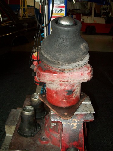
Removed unit can then be bench mounted and dissassembled using a large Phillips screwdriver and a 14mm spanner.


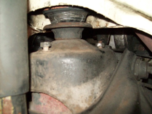
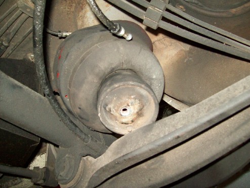
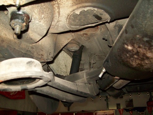
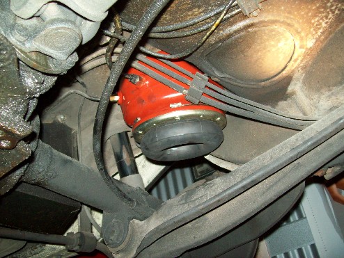
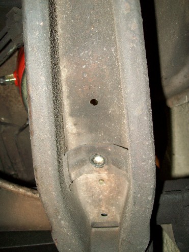
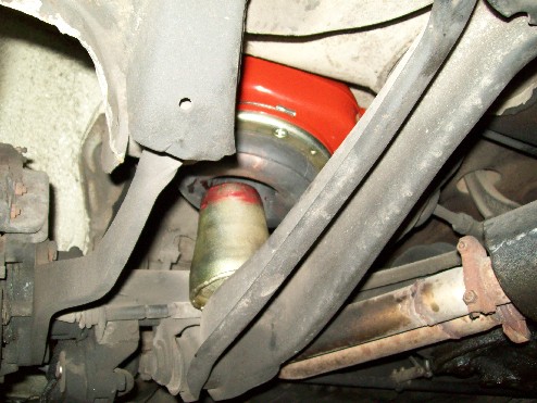
Now the rear units. Wheels off, view from rear on right.


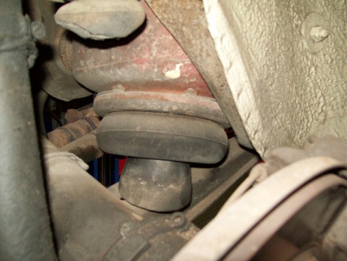
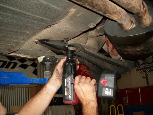
Undo the bolt holding the piston to the trailing arm and dislocate the piston.


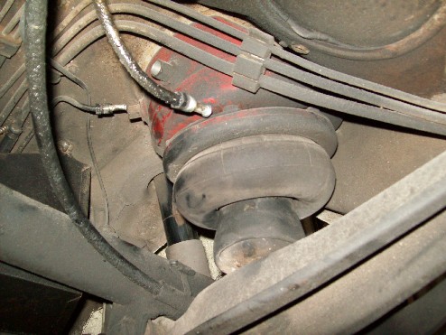
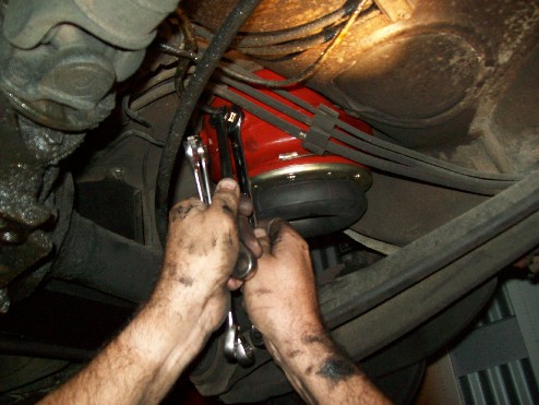
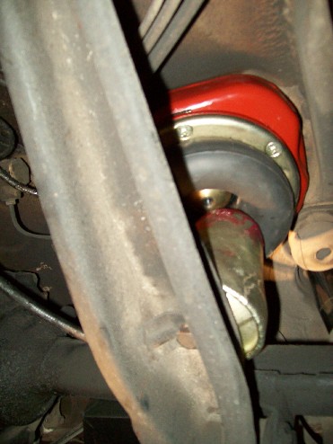
Undo the air lines. This is on the left.


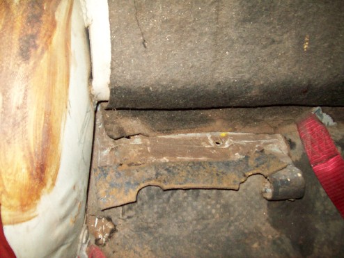
Send slave into the boot (trunk) with a 13mm spanner to undo the nuts at the right and left front corners of the floor and another slave into the rear of the car to remove the rear seat base. In the coupe, I found it necessary to remove the seat rear as well. There are two nuts and washer sets on each side. The sound deadener had to be lifted to get to them.


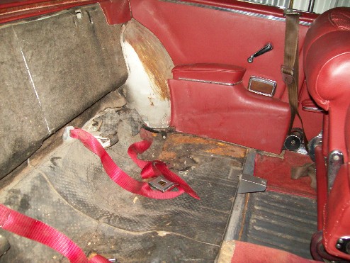
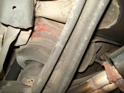
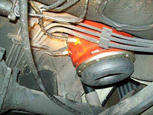
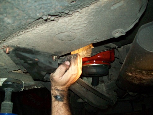
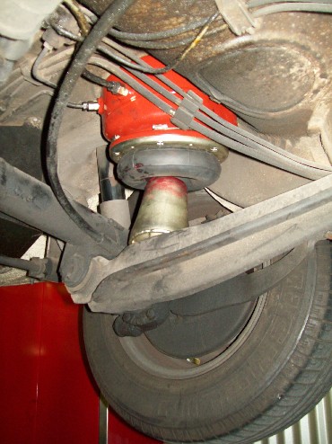
Drop the tank unit down from the floor. On the left, the whole unit came out quite easilly. On the right in the coupe, the exhaust was in the way. We got the right unit out by dropping the front of the trailing arm. Here's the left side.


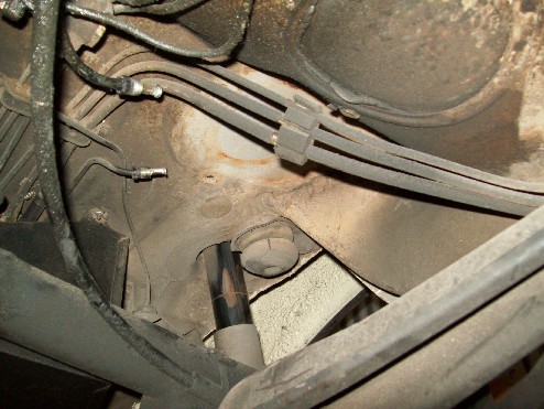
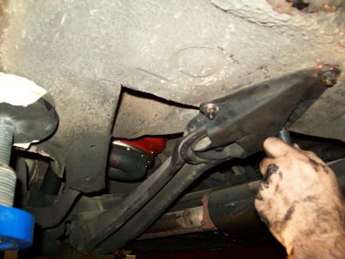
Here's the right unit going nowhere.


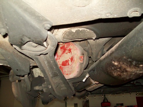
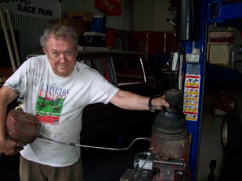
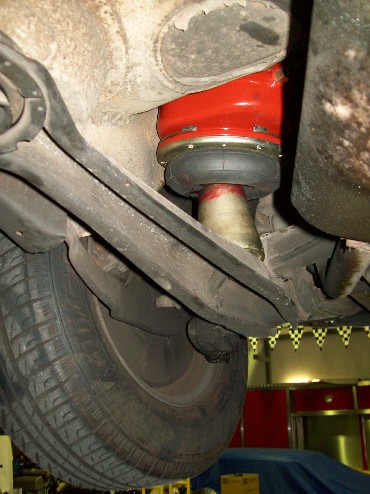
Here is the solution.


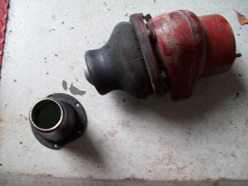
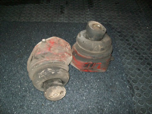
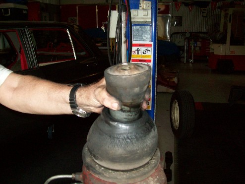
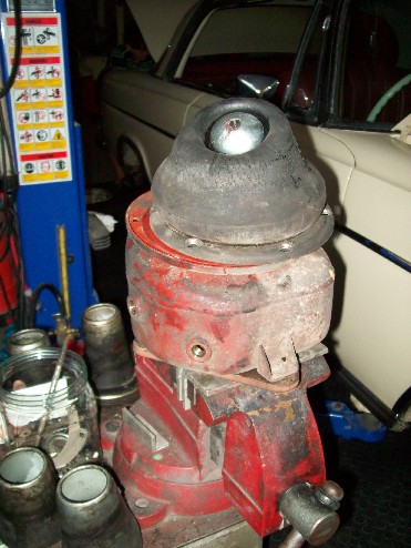
Both units are out and you will notice that we did not try to remove the pistons from the bellows on the car. Getting these pistons out is the worst part of this job after many years of use. They really stick to each other where the top of the cone seats in the rubber and steel "lid". The rear pistons are closed at the bottom, so bashing them off the bellows with a drift was not an option.


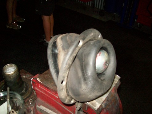
So I decided to use the same method I used 20 years ago of blowing them off using the rolling action of the bellows. This method only works if the bellows don't have holes in them. I put a Shrader valve into the inlet line of the left tank and used the spare cross line to connect the two units. Other option is to make up a service line with your compressor fitting on one end and a spare end of steel line with screw fitting. You need a larger fitting for the rear tanks if you go that way. I think I put a picture of one of these service lines way back in this thread. If not I'll add it later.


Dissassemble the units on the bench as per the front units.


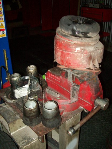
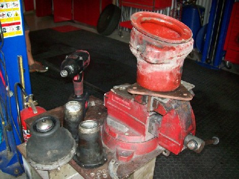
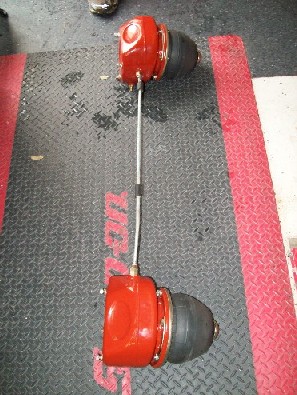
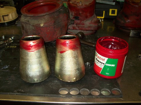
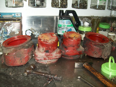
Collect all screws, stiffening plates, retainer rings, pistons etc and send to zinc plater for gold zincing. Clean and repaint steel air tanks, buy new bags. Reassemble as per the start of this thread and "bingo" you have rebuilt units to pressure test. Here are a couple of rear units ready to test with 50psi in them via a temporary Shrader valve.


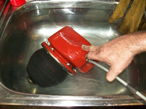
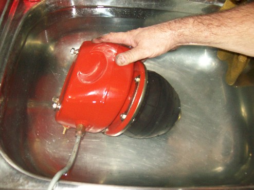
Now they are in the sink.


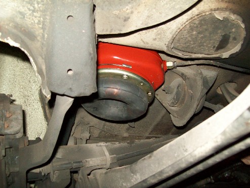
Locking tabs turned and now they are back on the car, thanks to the slaves in the boot and the rear seat.


Air lines reconnected using proper tools and new washers.


Prepare the rezinced pistons. The Service Manual says to use glycerine as I recall. I used rubber grease.


There is a pin on the bottom of the rear piston that goes in a hole on the trailing arm and the rear pistons are stamped R and L to make installation foolproof.


Screw in the bolt.


On the right we had to reattach the trailing arm.


Wheels back on.


Then we have 4 tanks to clean and repaint for the next job. I am stalled on the front unit reinstallation because the 4 control arm buffers I thought were there were not immediately available and it was getting late. We want to install the buffers before replacing the bellows units.


So that is it for the moment. I hope someone finds it useful. I'm doing a printed version in sections for the Lode Star.
Art
mtrei
Vascular surgeon Dr Arthur Love demonstrates the latest in pneumatic heart valve technology.

Art Love
I'd suspect that the technique has more application in urology[:D].
Art
abl567
You taking the piss Art[:p]

300SEL
6.3 #2723, my first classic Benz
3.5 #8659, my second.
2 to go...
Ron B
No need for viagra with that metal tube,just get your 'assistant'to blow up the bellows when the need arises...[:0]

quote:
12-14-2004, 11:49 PM #8
Tom Hanson
MBCA Member

What the heck, try to stuff a MB 6.9 liter V8 in it. What a machine that would be..
__________________
Tom Hanson
Orange County Section
Craig Tucker
With abit more rubber grease, that cathitar (checks spelling)/siposetry could fit almost anywhere. Don't like the "this is going to hurt" smile on the surgeons face....lol.

C.T.[B)]

1969 300SEL 6.3 (to be AMG 6.8 replica)
1971 300SEL 6.3
1993 300E-24
1959 220SE Ponton
1983 Schuler 5.0lt Range Rover
Art Love
The coupe bits are back from the plater.


Justin has been looking for some alternate screws and nuts. The nuts are the thin DIN 439 type.


This is what I am talking about with regard to these thinner nuts. On the left is the old 14mm DIN439, in the middle the current 13mm DIN439 and on the right the current 13mm DIN934.


So as to stop any more lewd jokes about my activities, he has also had some little things made to allow pressure testing without having to use my spare rear cross pipe[:p]. Here is a sample of the bits and their application. I'll cover it in more detail in the Lode Star.


Art
Chris Johnson
Art, since you mentioned the DIN 934 nuts, should I assume that these are what was on the tanks when you removed them? Of course, the factory never used DIN 934 nuts in this application.

For the record, DIN changed the 8mm parts (nuts and bolts) somewhere in the mid-'60s such that the span across the flats went from 14mm to 13mm. These 13mm parts started to show up in production in '65, but 14mm parts still show up on cars occasionally even into the late '60s.

DIN also changed the way these parts were marked. Prior to the change, markings were always in the form of "number-letter". i.e. "5S", "6S", "8G", "10K", etc. After the change, markings took the form of "number-dot-number", i.e. "8.8", "10.9", etc.

Folks seriously concerned about originality need to look out for these details when disassembling anything on the car. There was a short period of time when the distance across the flats on 8mm parts had already changed to 13mm, but still had the early style markings. These are the rarest of the rare where hardware is concerned.

Chris Johnson
If you aren't constantly impressed with your car, then it needs fixing.
100.012-12-000790
100.012-12-000867
www.300SE.org
Ron B
Pontons are full of those early DIN standard fastners. It often get caught trying to fit the wrong size thread ( but correct size head) .On a W109 a 10mm bolt will be have the same size thread as the next 10mm bolt but on a ponton a 10 mm head may have a 8mm thread. I have bags of bolts from both of my roundies and I have to make sure that the bags are marked to show where they came from. No zinc or cad plating on these older cars either.

quote:
12-14-2004, 11:49 PM #8
Tom Hanson
MBCA Member

What the heck, try to stuff a MB 6.9 liter V8 in it. What a machine that would be..
__________________
Tom Hanson
Orange County Section
Art Love
Chris,
The 934 nuts hold the metal tanks to the car body work and front subframe which is why I had one back from the plater to use for the picture. I put up the picture to demonstrate the difference. I thought I had mentioned the 439 nuts earlier in this thread, but going back through, I can't see it. I have gone into it in some detail in the Lode Star article Part 1 in the next Lode Star including the typo in one of the Parts Manuals.

In fact, all the nuts on the coupe were correct 14mm DIN 439. What wasn't correct was the total absence of lock plates. On the front, the previous bag changer had used star washers and you can see the imprint of the washer in the 14mm nut on the left of the three in the picture. Whoever did the rears used standard split lock washers. Justin's 6.3 had lock plates and a combination of 14mm and 13mm 439 nuts, probably because some of the nuts had been damaged and had been replaced. On that car, someone had welded some of the nuts!!!
Art
Chris Johnson
I've occasionally seen 934 nuts used to hold the rings to the tank, and it isn't to replace one or two missing 439 nuts. For what ever reason the last guy replaced all the nuts with the wrong ones(?).

Like you, I have also seen these nuts welded to the flat brackets. I can't imagine why. It seems so much easier to just use a DIN 127 lock washer if the original lock isn't reusable. And, of course, the original style locks are, and have always been, available new.

Chris Johnson
If you aren't constantly impressed with your car, then it needs fixing.
100.012-12-000790
100.012-12-000867
www.300SE.org
abl567
Quote "Justin's 6.3 had lock plates and a combination of 14mm and 13mm 439 nuts"

I'm in the process of changing my front bags as well and found 2 13mm nuts and the rest 14mm on the passanger side chamber, they were in one of the tighter spots so I assumed it was due to space issues.

As far as getting the bag through the ring...I gave up trying yesterday and will enlist the help of a much stronger set of hands belonging to one of my staff on Monday[:I]


300SEL
6.3 #2723, my first classic Benz
3.5 #8659, my second.
2 to go...
Art Love
Anthony,
I understand your grief with those air bags. When I did the ones on #1702 15-20 years ago, I recall struggling "for hours" down in my garage on my own using every trick I could think of. Vascular surgeons fingers are not much good for this. Orthopaedic surgeons would be OK[:D]. It is great having Justin push one through in a minute or two.
Art

Art Love
The new buffers arrived today, so we got on with replacing the front bellows units. Here are the buffers going in. This is a bit of a fiddle because the bottom of the rubber is wider than the top, as are the metal cylinders they go in. Plenty of rubber grease[:)].


I also replaced the completely destroyed nylon ball joints on the airvalve control rods with some second hand steel ones. I'm waiting on an order of new ones from J.W.Winco Inc in Wisconsin who still supply the original German steel ones. But at least this will let us get the car off the hoist and moveable. The following pictures show the air suspension units going in. As with getting them out, we managed from behind the axle without undoing the tierods. We've used stainless steel screws, washers and nuts on the pistons. I've got new screws coming from Tom, but they are not here yet and I can use them on another car. I overdid the antisieze grease a bit. I'll wipe it off when we do the front sway bar[:I].


Well, that is pretty much the job done. Hope you all enjoyed it. As I said, I'm doing a series of articles in the Lode Star because Jack English said I should and we should all be supporting Anthony with articles. Not everyone looks at this website, and it gives a printed version with high resolution pictures.
Art
Art Love
Just when you think you are finished, there is always something else. This series covered the W112 and W109 cars. On the 600 forum are some views of the same thing in the 600 which is somewhat different in the detail if the same in principle. It's in my thread on detailed views of the 600.
Art
FEMA
Art, this is super especially since I am planning to do this project. Now, what I am wondering is this - is this the procedure just to replace the airbags? Meaning, do I have to remove all the hardware as you did whether I paint them or not?

It's certainly a good idea to address all these pieces while you are in there and I'd like to do the same. Right now of course I'm wondering if I am up against time before the meet, plus I need to replace some valves which I assume are no big deal[?]...so I need to look into this as well.

My bad for procrastinating[:I]

Francis E. Abate
Art Love
Hi Francis,

It is much easier to replace the air bellows on the bench rather than on the car in a 6.3. On a 600, I don't think that is necessarilly the case because the system of attachment is different. The rear pistons are held on with one bolt and washer and the rear tanks by three nuts and washer sets. You can reach the rear nuts at the front of the trunk and the front two by taking out the bench of the rear seat.

On the front, the piston is held to the lower control arm by 6 bolts and nuts. The only special tool you need is a right angle flat bladed screwdriver to hold the screws while you undo the nuts and washers. The air tanks are atteched at the top by three nuts and washer sets. - 13mm, same as the nuts in the trunk and under the rear seat.

Trying to undo the screws, nuts, lock plates and stiffeners with the metal tanks on the car will drive you nuts. I noticed that Paul Jermy had his tank bolted to a piece of ply rather than my special tool set up. There are plenty of ways to skin a cat. My advice is the remove the units, give everything a good clean, rezinc the plated items if you have a local plater with a quick turnover, just clean if you don't. Preorder a set of lock plates from Tom Hanson as well as a few spare nuts, screws and washers just in case and go for it.

Yell if you have a problem[:)].
Art
FEMA
Sounds good Art...I don't yet have a lift so I imagine this makes it a bit more difficult but so be it. Any more hints regarding only having stands to work with let me know.

Also, I have two bellows from the parts car I bought which were new and in the trunk, do these have a shelf life such that I should not use them?

Francis E. Abate
Chris Johnson
Hi Francis,

I will back up what Art has said whole-heartedly. On a W112 or W109, remove the tanks from the car!

There are varying challenges the first time you try to do this. I would suggest starting with the left-rear tank first since it is the easiest to remove and reinstall. This will let you get some experience changing a bag before you also have to fight with the additional challenges of removing and re-installing the tanks at the other three locations.

There are some typical problems that you should anticipate. The line nuts that secure the steel lines into the tanks can be impossibly tight. I recommend using a good quality penetrating oil on these fittings and line nuts before attempting to loosen them. Personally, I like Kroil (or Sili-Kroil). It is expensive and not readily available at most auto parts stores, but it can be bought on-line. The manufacturer also frequently runs promotions that allow you to get one can for free so that you can try it out. I have found that, in most cases, keeping a fastener wet for about twenty minutes is the best (badly rusted stuff can require much longer).

The next requirement is to have the right tools in advance. With the exception of the larger diameter line between the rear tanks, all the rigid steel air suspension lines have a 12mm line nut and the line nuts thread into adaptor fittings that are 14mm. The adaptor is fairly hard metal and can be dealt with with a standard 14mm open-end wrench. The 12mm line nuts, on the other hand, are made of a much softer material, and rarely come loose with a standard 12mm open-end wrench. This usually results on a line nut with the flats rounded over and still tight. A "flare nut" wrench is the best way to start with these line nuts, but not a cheap one. An "easy-to-get" Craftsman wrench is not the right tool for this. A much more expensive Snap-On wrench is appropriate, but, even then, this is still a flare nut wrench and if leaned on hard enough it will still spring open a bit and can damage the line nut flats if pushed far enough. This should not be a problem unless the hardware parts are badly rusted. The tool of last resort is Vice-Grip pliers run down to a very high clamping pressure.

You will usually find that, if trying to loosen the line nut without also having the adaptor fitting held with a wrench, that the adaptor fitting will unscrew from the tank before the line comes loose from the adaptor fitting. One needs to watch for this so that he does not make the mistake of thinking the line nut is loose and continuing to "unscrew" the line nut with the wrench only to actually twist the line to the point were it breaks. This can also be a problem in badly rusted situations were the line nut comes loose from the adaptor fitting but the line nut is solidly rusted to the line itself.

Since you would be starting with the left rear tank, you have to deal with two line connections (unlike any of the other tanks). The second line connection is the line to the right-rear tank, and the line nut is 14mm and the adaptor fitting is 17mm. Same problems, same solutions. But, once the line connections are loose, the left rear tank will come out easily once the three nuts holding the tank to the chassis are removed.

Next is the right rear tank. This is a bit of a pain, and it is best to drop the front end of the right torque arm. Other than that, it comes out the same way as the left-rear tank.

The front tanks are not overly difficult to do, and different folks use different methods to remove them. Personally, I prefer to remove the outer ends of the tie-rods (with the appropriate tool, not a pickle fork) and leave the front suspension hanging low. With the piston loose from the lower A arm, the piston can be easily pushed up into the old air bad leaving plenty of room to remove the assembly from behind the subframe. When re-installing the assembly, do not include the piston. Once the tank and bag assembly is fully installed, the piston can be easily slide up into the bag and onto the lower A arm.

Note that the original slotted screws that secure the piston to the lower A arm are no longer made! Certainly, there are others that will work just fine mechanically, but for us folks that appreciate originality it is important to be gentle with these screws so that they can be re-used.

Modern air bags do have a production date cast into the rubber. This has the form of "month" - "year", both in two-digit form. You will find this on the outer surface just below the sealing rim. If your spare bags do not have this production dating, then they are very old. If they do have the dating, then you can tell when they were made. Personally, I won't install anything more than a few years old, but then, I don't have any spares sitting around either. If you find the dating and it is more than a few years, post the date and we can speculate about their suitability for the task.

Having moved entirely too many times, I have no idea where some of my special tools are. While a rigid base for the air tanks is nice, it is not necessary in order to remove and re-install the bags onto the tanks, so don't be concerned if you can't come up with an easy solution to that problem.

Removing the nuts and bolts around the perimeter of the bag clamping ring on the tanks should be done by unfolding the lock plates from the nuts and then loosening the nuts with an open-end wrench, but sometimes it is very difficult (read impossible) to loosen the nut this way. In this case you can try to loosen the bolt instead, using a typical auto parts store hand operated impact driver. Don't start smacking the thing with a five pound mallet, but a regular hammer is usually sufficient to loosen the bolts.

Chris Johnson
If you aren't constantly impressed with your car, then it needs fixing.
100.012-12-000790
100.012-12-000867
www.300SE.org
Chris Johnson
One other thing.

I have never had this problem on a 109, but it comes up frequently on a 112, though I have to imagine it could happen on a 109. After a rear tank/bag assembly is re-installed on the chassis, the piston is installed on the torque arm. The rear axle is usually hanging down, so, so is the torque arm and piston. The piston is not well aligned with the bottom of the air bag. Once the rear wheels are reinstalled and the car taken off the lift or jack stands, it is not easy to see the piston and therefore not easy to see if the piston did align properly with the air bag. If it did not, the bag could be inflated and actually lift the car off the ground, but it would be the outside rubber sitting on top of the piston, not the center of the bag. I wish I had a picture of this. Obviously, this would destroy the bag in short order.

Ideally, the rear suspension will be resting with the axle tubes "straight out", in their normal driving condition. This will better align the pistons with the bags, and this is the state in which the system should be re-pressurized in order to guarantee that the bags mate with the pistons properly.

Chris Johnson
If you aren't constantly impressed with your car, then it needs fixing.
100.012-12-000790
100.012-12-000867
www.300SE.org
FEMA
Chris;

Thanks so much for the thorough explanation, and having the right tools is a must I agree - been there, done that and wasted plenty of time[:o)] I will try to gather the right stuff and get started.

Should we start another thread on the valve's (maybe there is one if I search) or do they just get replaced without any special adjustments? I know I have at least 2 leaking from a previous diagnosis and figuring these will be addressed with the car up as well.

Francis E. Abate
Chris Johnson
It may be better to start a new thread on that topic. If precise height setting and control is not particularly important then the valves can simply be replaced, but to set and determine that everything is exactly right is not a small topic.

Chris Johnson
If you aren't constantly impressed with your car, then it needs fixing.
100.012-12-000790
100.012-12-000867
www.300SE.org
Art Love
Francis,

You will find pictures of most of the things Chris said in this thread.
Art
Art Love
Francis,

There is a particular trick to undoing the air lines without which you will not succeed regardless of having the correct tools. The same "trick" also applies to any similar fitting such as the water pipes where they attach to the fittings on the engine etc. Chris has not specifically mentioned it. He has stressed the importance of the correct tools.


These 3 plus a standard 17mm and 19mm spanner do most jobs. The pipe spanner at the top is critical for standard air lines.

The trick is to position the two spanners so that you can squeeze them together with one hand. In other words, they should be positioned so that they are at an angle to each other of about 20-30 degrees and so the 12mm spanner on the pipe end fitting will rotate in the direction that undoes the end fitting. Here are a couple of photos showing what I mean. One of them is in the thread, I'm adding the second now.


Always position the two spanners so the one on the fitting you are trying to undo rotates toward the one you are trying to hold still. Always squeeze the spanners together, not away from each other. This gives a very controlled force and reduces the likelihood of rounding off the fitting. If the fitting is already rounded off and the pipe spanner won't hold, then you have to use a vice grip like Chris said.
Art
Chris Johnson
It never occured to me to specifically mention this, but I do it on a regular basis. There are locations where it is just not practical to get two hands in there, and, as Art says, it is a much more controlled action than can be accomplished with two hands.

There are also times when it is advantageous to flip the flare nut wrench over so that it "leans" toward the other wrench rather than leaning away from it, if there is enough space to do so.

Chris Johnson
If you aren't constantly impressed with your car, then it needs fixing.
100.012-12-000790
100.012-12-000867
www.300SE.org
FEMA
Ok Art / Chris - I understand and just want to confirm those tools Art shows in the picture are flare nut wrenches, hex shape as shown right? I asked because it's hard to see the flat (hex)sides of the 17mm (maybe well used [:)])so I was not sure if this was some other special shape to it.

I see the middle is a standard 14mm, not flare.

I'm going to ask my neice who is a trained BMW mechanic in NJ if she has these tools in high grade manufacurer like Snap On. If she does not for some reason do you guys think NAPA or Craftsman carries a higher grade that would do the job? We do have a local Snap On rep that lives in the area so I will go to him if I have to...just want to be sure and get your confirmation.

Looking forward to this challenge[:D]

PS - just found the old bags[:)] that are unused they have the following markings, Phoenix Harburg, 1A04, and date coded (?): 1281 & 0183...and these two are the smaller ones which assume are either front or back???

Francis E. Abate
cth350
My craftsman flare wrenches have lasted me 20 years. The one I adore is the SK (as it's even beefier). Got it at a garage sale.

Didn't Ron post pictures of a new range of snapon "brakeline" wrenches?

HTH -CTH
Chris Johnson
The top and bottom wrenches are flare nut wrenches, the middle one is a standard wrench.

The 1A04 bags are front bags, and with those production dates (12/1981 and 01/1983) the only thing they are good for is display case items.

Charlie, I agree with you that those old Craftsman tools are just fine, but the modern stuff is crap. Craftsman seems to have gone the way of so many other fine manufacturers and sacrificed quality in exchange for price. Francis, I wouldn't waste the money on Craftsman or anything available from NAPA. If it doesn't say Snap-On or some very well known European name, don't waste the money.

Chris Johnson
If you aren't constantly impressed with your car, then it needs fixing.
100.012-12-000790
100.012-12-000867
www.300SE.org
FEMA
Art / Chris;

A couple of questions as I read through this an get ready:

1. Art - didn't Craig Tucker describe a method to us in Steamboat for removing the front bellows that was different than this, something about loosening the control arm or wheel so the wheels could actually swing up and away from the car? Just curious in the event this is an alternative to what you show or if my memory is totally wacked[:I]

2. Is this a good opportunity to replace the front subframe mounts? Mine were done when I bought the car but again thought this might be of interest if it's clearer to do this job with airtanks off.

Still digesting the rest while I order parts and prep[:p]

Francis E. Abate
Art Love
Francis,
I don't recall Craig talking about this. I wonder if he was talking about a 600 based on your description. I would not do this job with the wheels on regardless of model. It may be necessary to release the tierods at their outer ends to get the front units out. We managed without doing it on the 300SE. The geometry on the 6.3 is a bit different.

I can't see any benefit one way or the other in dealing with the subframe mounts at the same time unless it is your intention to take the whole front subframe out to do other work. If they were new when you bought the car, they probably don't need replacement and replacing them does not in any way that I can think of, assist the air bellows replacement job.

Others may disagree, but those are my thoughts.
Art
Craig Tucker
Art, Francis and others,

A very quick and simple way to remove the Air chamber complete with bellows and leaving the piston on the lower A arm is to;

a) remove wheel from side of bellow to be replaced.
b) Undo Swaybar connecting rod (13mm) with an air wrench.
15 seconds and disconnect lower control rod from air valve.
C) Undo the inner four (4) mounting bolts (19mm) of the lower A arm
with a rattle gun. 30 seconds
d) swing lower A arm complete with piston, to the outer of car; pivoting on knuckle. (I use compressed air, shot up between the piston and the bellows to "free" the bellows from the piston)
e) remove chamber complete with bellow by undoing 3 13mm nuts and 1 air line. 2 minutes.

Of course, this is far easier on a hoist.

C.T.[;)]


1969 300SEL 6.3 (to be AMG 6.8 replica)
1971 300SEL 6.3
1993 300E-24
1959 220SE Ponton
1983 Schuler 5.0lt Range Rover
Art Love
Thanks Craig,
That must have been what you told Francis in Colorado.
Art
Return to Forum