The members of this forum have been tremendously helpful to me in the past and generous with their knowledge, so I thought it time to impart the knowledge that I have built up over the last ten years of so regarding the overhauling of air control valves. Contrary to my misanthropic views, I think it’s important to share this sort of information for the benefit of all to keep these cars on the road. I don’t think everyone can afford to get this done through a specialist, and I’m hoping the info below will allow you to be able to tackle this job yourselves – if you are already working on the car yourself, you should be able to do this job quite comfortably.
Firstly I want to make it absolutely clear that I am not, nor claim to be, an air suspension specialist. Ten years ago there was very limited information about air control valves on the web, and I used this limited information, pure deduction and some mechanical experience to find the solution to overhauling air control valves which has turned out to be successful. I’m sure that there are far more pedantic members on this forum who have worked out exactly the correct seals to use and all the exact specifications – please understand that I’m not taking anything away from them. However, I have found the air control valves pretty straight forward and have done it very successfully for myself and a number of people here in South Africa with over-the-counter seals.
I don’t overhaul valves for anyone anymore, mostly because I have so little time to work on my own cars and I can only ever do this over the weekends. Also, most people who tell you “to take your time, I’m not in a hurry” are the people who phone you three times a day and I honestly don’t need the hassle.
My story began twelve years ago when I bought a W112 300SE coupe, which obviously had faulty air control valves – the suspension dropped within minutes of switching the car off. I didn’t have a clue at that stage how to remedy this. But I was put in touch with a local ‘specialist’, who overhauled the valves for me – it took about 6 months to get them from him. They seemed to work okay, these valves being the original simple valves to be found on the early W112s.
I was already looking after a friend’s 6.3, which started to develop problems with the front air control valves, so I took them out and sent them to the same ‘specialist’, who charged and arm and a leg to overhaul them - they were no different. I couldn’t get my money out of him, and just left it at that.
I then bought a 600 which also needed the control valves done. I was definitely not going to send them to the previous ‘specialist’ and I considered sending them to Star Motors. Problem was that our exchange rate was/ is so bad that it would have been almost unaffordable at that stage. I had one or two extra sets of valves, so I decided to see if I could do the job and through lots of trial and error, I managed to do so.
I can confirm what most of the guys have said on the forum in that 99% of the problem with air suspension lies with the air control valves, and this is what I’ve worked out:
1) If the car’s suspension drops within a few hours/ days of the car being switched off, but pumps up to normal ride height when the motor is running again, then the problem invariably lies with the air control valves.
2) If the car is running and the suspension doesn’t lift, then there are a few possibilities:
a) The bellow is split and air is escaping
b) The bellow holds pressure, but the connecting pipe between the air bellow and air control valve is split
c) The connection on the bellow or air control valve is loose. In all of the cases above, you should usually be able to hear a hissing sound of air escaping when the car has been run for some time and is switched off.
d) The rod length between the air control valve and the lower control arm/ rear anti-roll bar is incorrect. This can be easily checked by unclipping the rod and moving the lever on the air control valve in an upward direction – the bellow should fill.
e) If none of the above is relevant, it is possible that the exhaust valve in the air control valve is stuck in the open position and air is continually exhausting – the air control valve will need overhauling.
f) Sometimes an air control valve can leak so badly that it doesn’t hold any pressure. Spray a dishwashing liquid solution onto the valve and look out for bubbles.
g) This is most unusual, but the air compressor may be wrecked and isn’t compressing any air.
3) If the car jacks up high in the normal ride height position, it could also be a faulty air control valve which is no longer exhausting. If you unclip the rod to the lower control arm/ rear ant-roll bar and pull the lever in a downward direction, the valve should exhaust and the suspension should drop. If not, the internal exhaust valve is faulty.
4) It is vital to check that the air pipes are all in the correct connections and must always be marked when being removed. I had an incident where the rear of a car just wouldn’t do anything, and eventually it was worked out that the air distribution valve inside the engine bay had been removed and the pipes were re-connected incorrectly.
5) Don’t under-estimate the use of a solution of dishwashing liquid and water brushed onto connections to determine air leaks.
Due to a lack of knowledge, people always seem to think that the air distribution valve inside the engine bay is the problem and usually set about tampering with it. This just compounds the problem. Or they think it needs new bellows, but the bellows are incredibly robust and really need to be totally knackered before they leak.
After almost 50 years of use, the seals within the air control valves have invariably become hard and I have sometimes seen seals on the internal one-way valves break like Bakelite when you try and pry them off. In my experience, most cars tend to drop at the front first and I think this is because the front valves are exposed to such continual high temperatures in the engine compartment. The rear valve tends to last a lot longer.
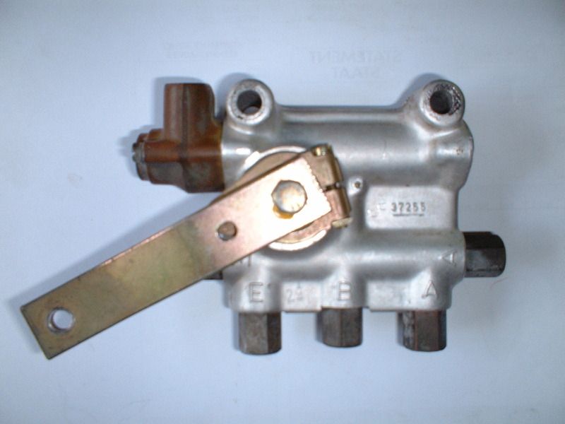
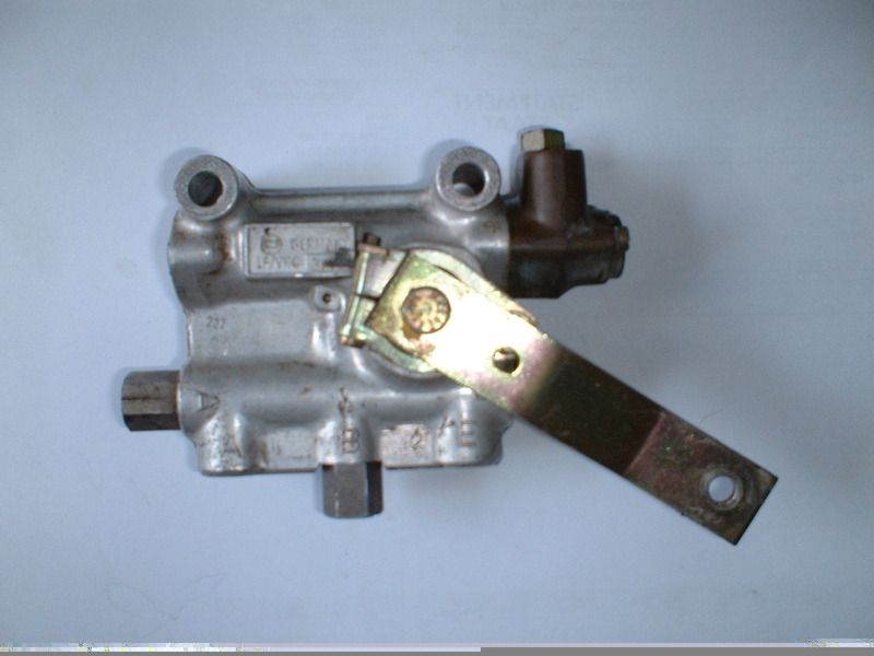
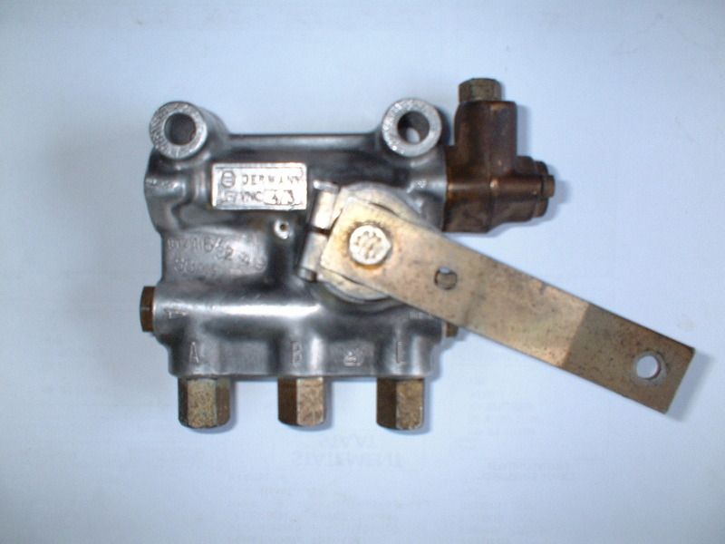
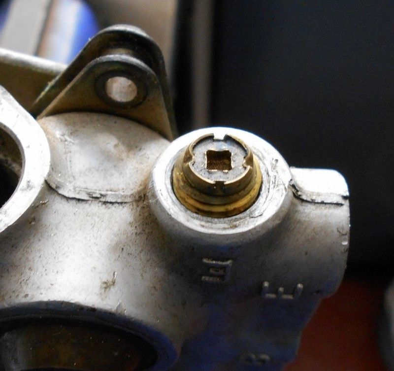
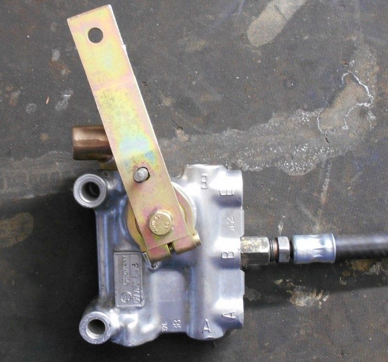
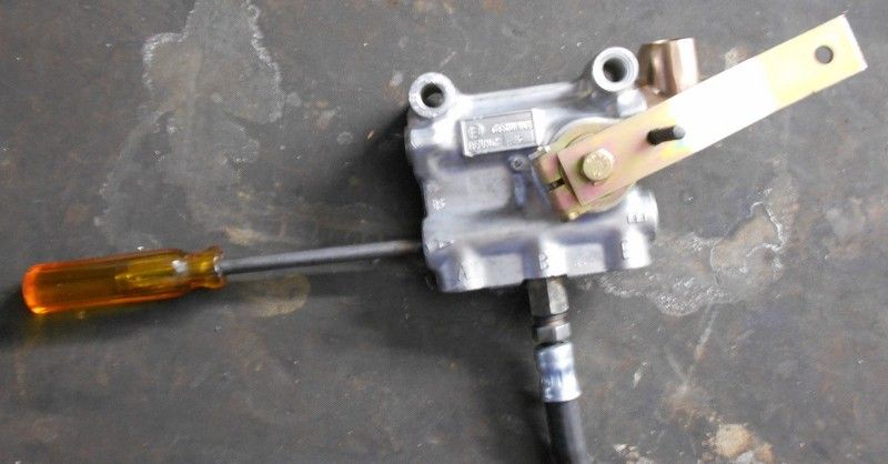
There are three control valves in the system: one controlling the left front air bellow, one controlling the right front bellow and one controlling both rear bellows. The air control valves are all of the same basic design, but all three are visually different, depending on which bellow they control. The left front control valve has connectors for the air pipes in all five holes, whereas the right front valve has only three connectors with the extra holes have been blocked off during the casting process of the valve housing. The rear valve also has three connectors, but uses two stoppers on the sides of the valve.
LEFT FRONT CONTROL VALVE
RIGHT FRONT CONTROL VALVE
REAR CONTROL VALVE
The front level control valves are rigidly mounted to the front suspension sub frame. The levers of the level control valves are connected to the front suspension lower control arms via an adjustable rod. As the suspension arm moves up and down, so the lever of the level control valve moves up and down, activating the internal one-way valves via an internal control arm, which either exhausts air from the bellow, or allows air into the bellow.
The rear level control valve is mounted to the body of the car and is connected to a lever on the rear anti-roll bar via an adjustable rod. This valve is mounted upside down as compared to the front valves. Similarly, as the rear suspension moves up and down, so the lever of the rear level control valve moves up and down, activating the internal one-way valves via an internal control arm, which either exhausts air from the rear bellows, or allows air into the rear bellows.
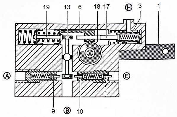
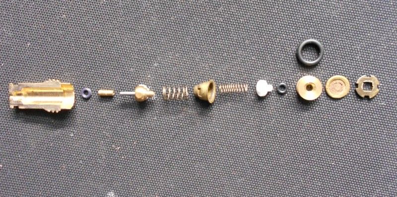
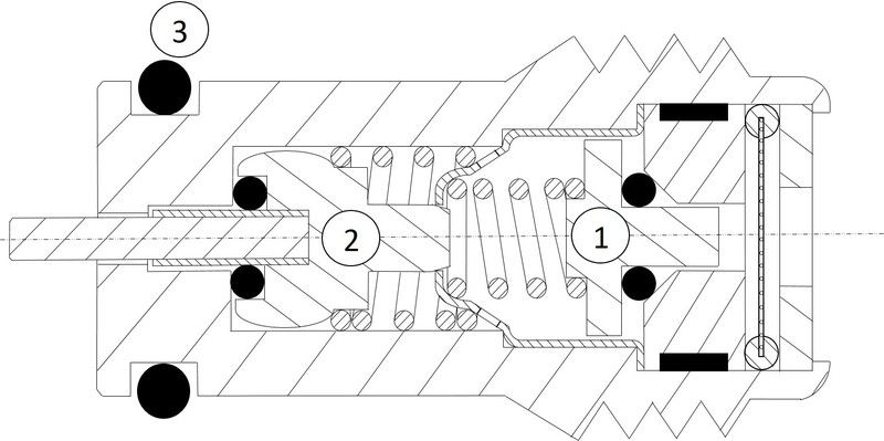
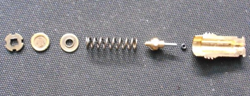
The control valve consists of the following components, as pictured below:
1) Control Valve Lever
2) High Level Cylinder
3) High Level Piston
4) Spring
5) Washer
6) Plastic Rack
7) Exhaust Airline Connector
8) Exhaust Valve Locking Screw
9) Exhaust Valve 10) Inlet Valve
11) Inlet Valve Locking Screw
12) Inlet Airline Connector
13) Control Bolt 14) Slide Piston
15) Sleeve 16) Bellow Airline Connector
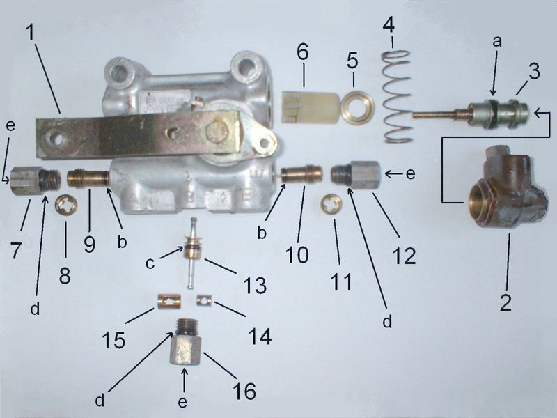
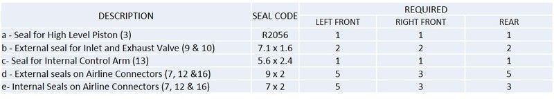
There are seals on certain components, which are essential to ensuring that the valve remains air tight:
- The High Level Piston (3) has an ‘O’ ring seal (a)
- The Exhaust Valve (9) and the Inlet Valve (10) both have the same ‘O’ ring seals (b)
- The Pivot Pin (13) has an ‘O’ ring (c). It also has another seal inside the brass housing. We’ll get into more detail about this one later.
- The Exhaust Airline Connector (7), Inlet Airline Connector (12) and Bellow Airline Connector (16) have the same external ‘O’ ring seals (d)
- The Exhaust Airline Connector (7), Inlet Airline Connector (12) and Bellow Airline Connector (16) have the same internal ‘O’ ring seals (e)
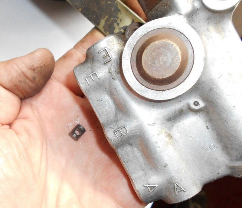
The level control valve is marked with three letters: (E) for Inlet or “Einlass”; (A) for Exhaust or “Auspuff” and (B) for Bellows. When the Inlet valve (E) is activated, pressurized air flows through the level control valve into the bellow. Similarly, when the Exhaust valve (A) is activated, air flows from the bellow, through the level control valve, into the exhaust airline. Both Inlet and Exhaust valves are one-way valves so that air cannot escape from the bellows, unless the valves are activated.
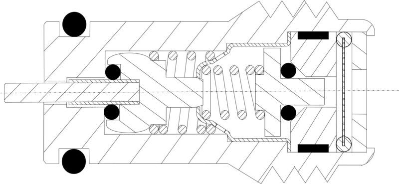
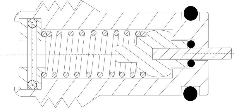
Here’s a schematic representation:
1) Lever
3) High Level Piston
6) Rack
9) Outlet Valve
10) Inlet Valve
13) Pivot Pin
17) High Level Piston Pin
18) Pinion
19) Spring Pin
The air control valve works in the following way:
Inlet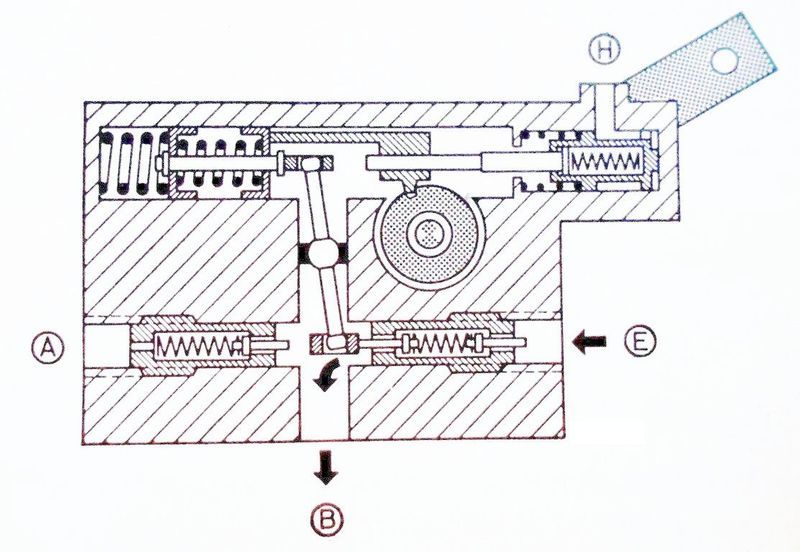
The Lever on the air control valve is activated by the adjustable rod connected to the suspension lower control arm/ anti-roll bar. The Lever is bolted onto the Pinion and as the lever moves up, it rotates the Pinion which moves the Rack left. The Rack pushes against the Spring Pin, into which the Pivot Pin is fitted. This pivot motion pushes a slide piston on the other end of the Pivot Pin, which depresses the pin on the Inlet Valve, which allows air to pass through the Inlet Valve into the bellow
Exhaust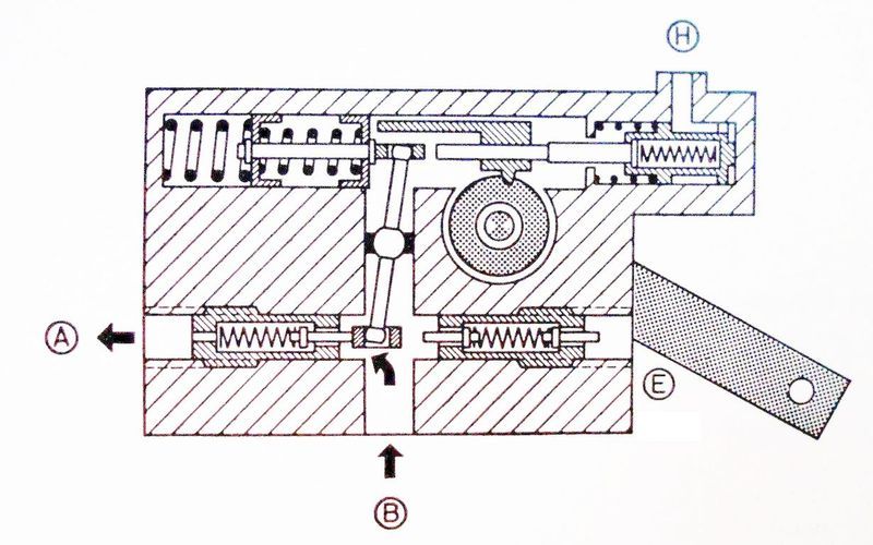
As the lever moves down, it rotates the Pinion which moves the Rack right. The Rack is pushed away because of the spring tension in the spring pin, into which the Pivot Pin is fitted. This pivot motion pushes a slide piston on the other end of the Pivot Pin, which depresses the pin on the Exhaust Valve, which allows air to pass through the Exhaust Valve from the bellow
Higher Level Setting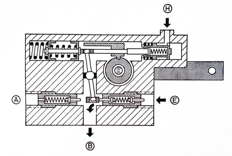
When you adjust the level control lever inside the car to the ‘H’ or High Level setting, the air distribution valve is activated via a cable connected to the level control lever. This then allows pressurized air to activate the High Level Piston at (H), which pushes the High Level piston left through the rack against the Spring Pin. The rack is therefore stationary and non-functional, but the action of pushing against the Spring Pin activates the inlet valve in the same manner as the normal inlet function does via the Pivot Pin.
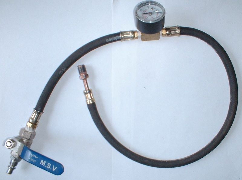
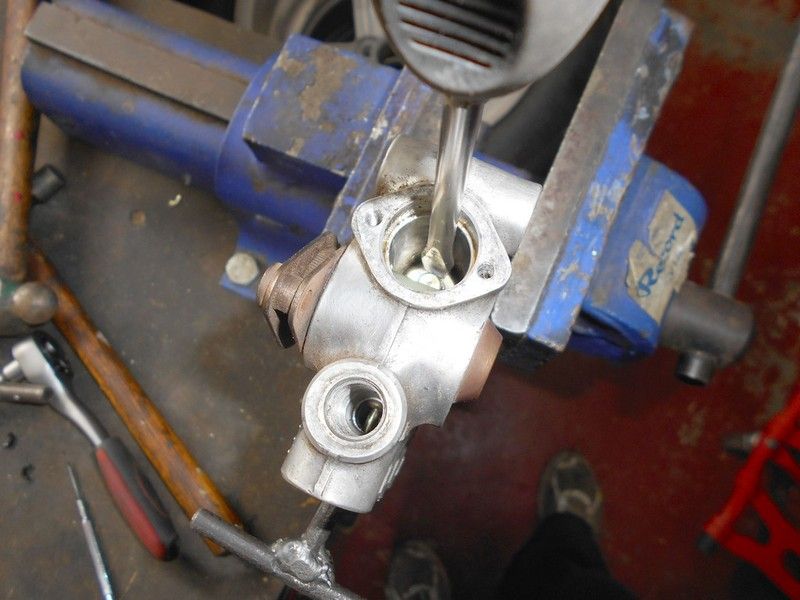
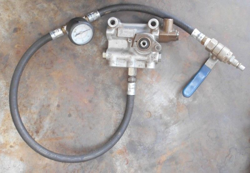
Overhauling the Air Control ValveThe first step is to have a pressure test gauge made. You cannot do this job without it and it’s one of three special tools to be made. The gauge should read up to about 12 Bar on a T-piece with two lengths of hose running from it. At the end of the one length is a threaded connection that can turn into the connectors on air control valve and on the other is a tap with a compressor pipe connector attached.
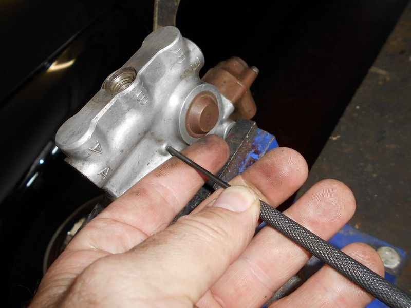
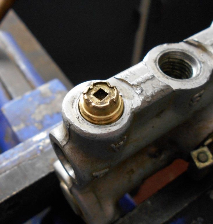
It’s important to see where the valve is leaking from, if at all. Insert a 4mm pin into the hole of the air control lever and the bracket on the housing, which will keep the lever in the neutral position, i.e. neither exhausting, not taking air in.
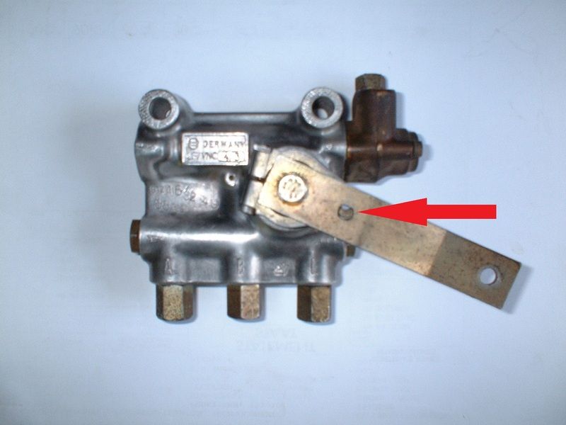
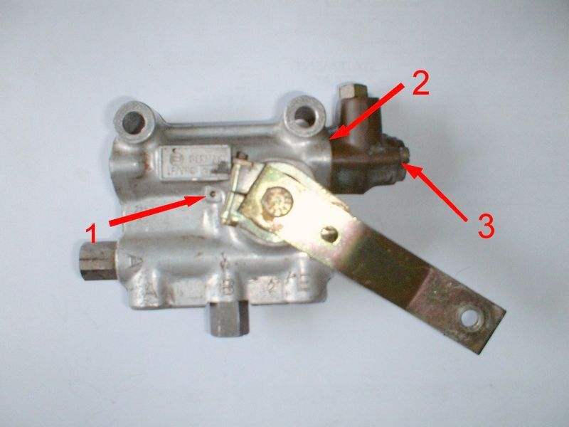
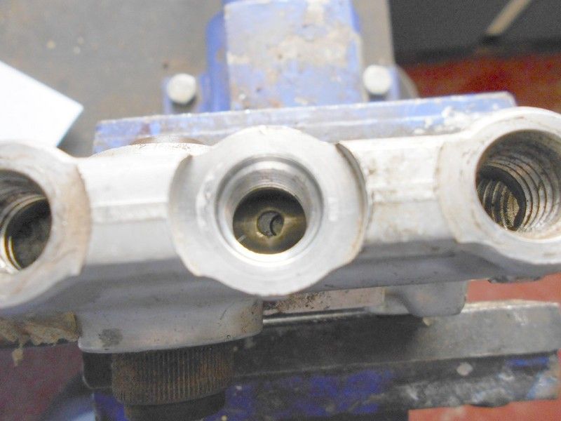
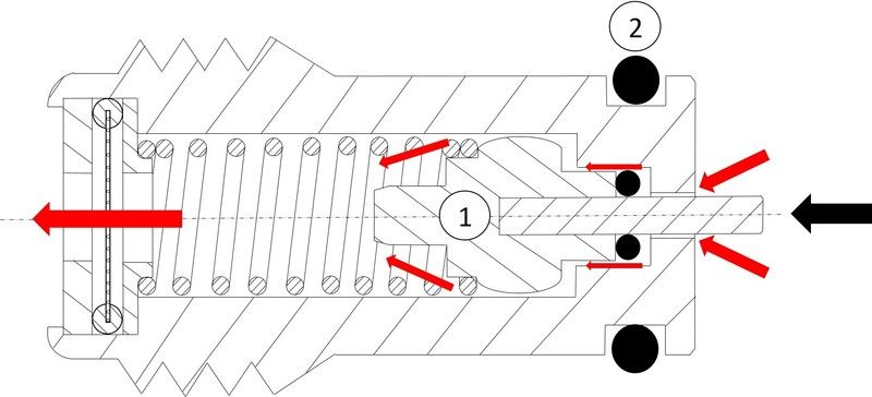
Turn the pressure gauge into the connector marked B, and hook it up to a compressor. Open the tap and then switch it off. If the gauge drops, the air control is leaking. Open the tap again to get full pressure and submerge the valve in a bucket of water. If air bubbles appear at any of the points in the picture below, the pivot pin assembly is leaking - usually the problem – and the air control valve will have to be totally disassembled to get it out to replace the seals:
1) At the pin that secures the pivot pin in place
2) Between the higher level piston housing and the air control valve body
3) At the screws that secure the higher level piston housing to the air control body
If there are bubbles from the connector A, either the one-way exhaust valve is leaking internally, or the outer seal on the exhaust valve is worn.
Likewise, if there are bubbles from the connector E, either the one-way inlet valve is leaking internally, or the outer seal on the inlet valve is worn.
Ensure that your work environment is clean.
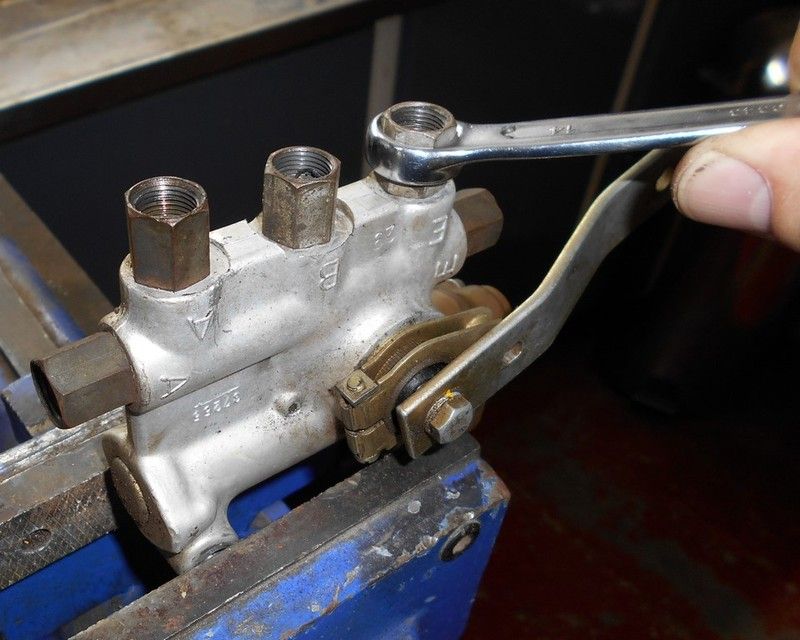
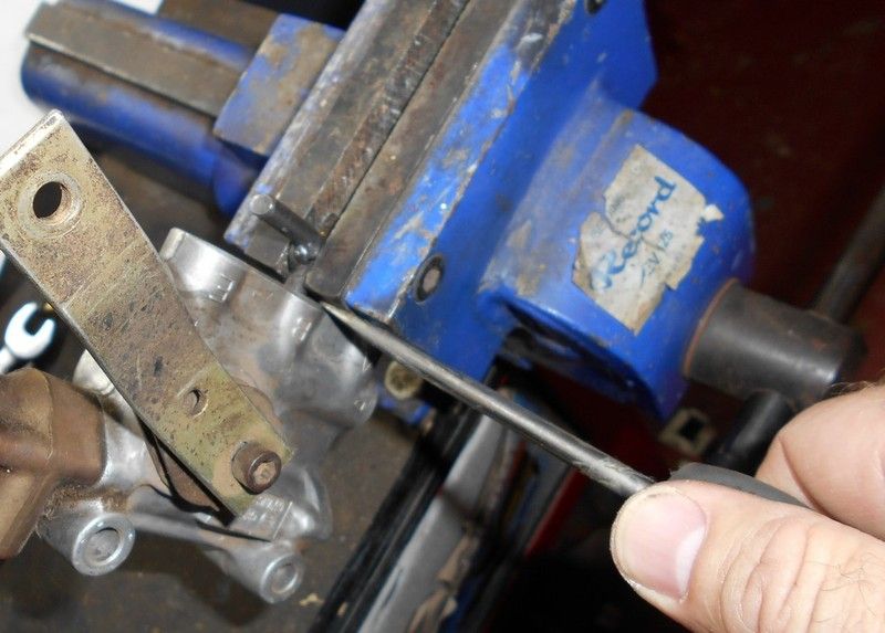
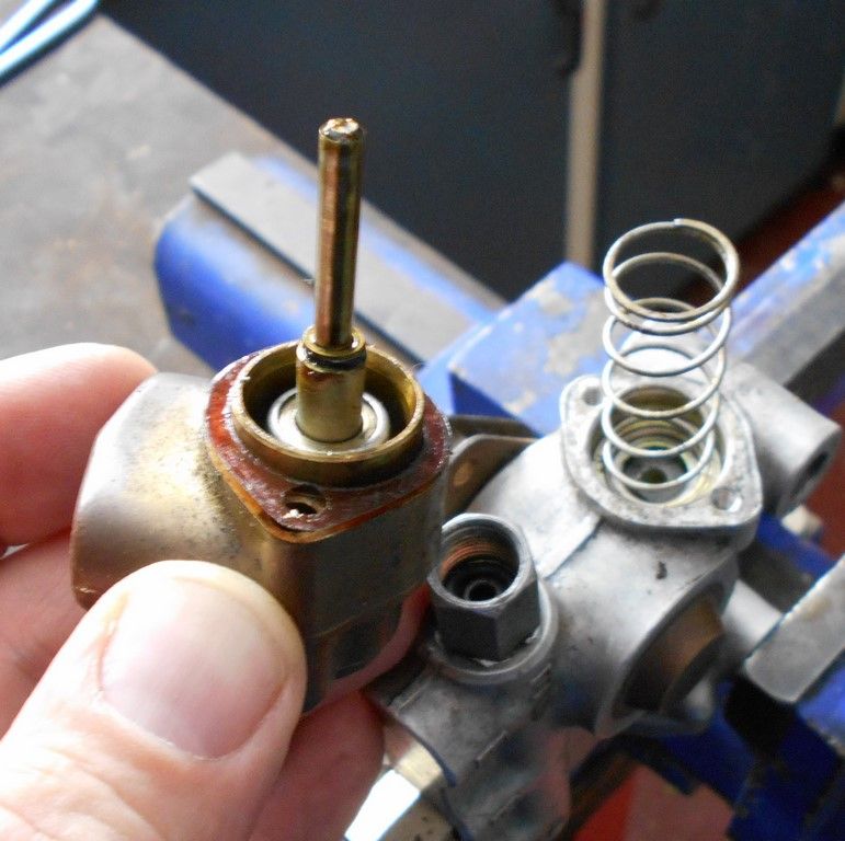
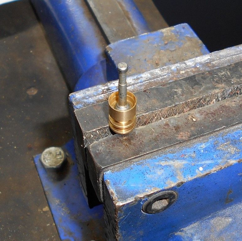
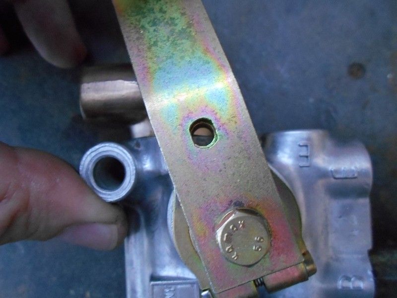
Start by securing the air control valve in a vice on its mounting holes and unscrew the air pipe connectors with a 14mm spanner.
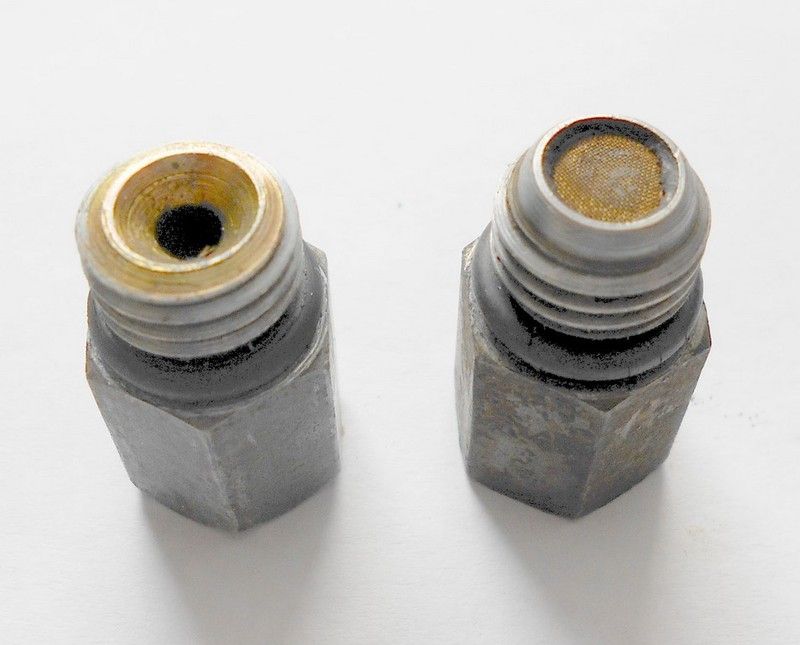
Note that the one air pipe connector on B has a gauze on the inside, whereas the other air pipe connectors have just plain holes through them.
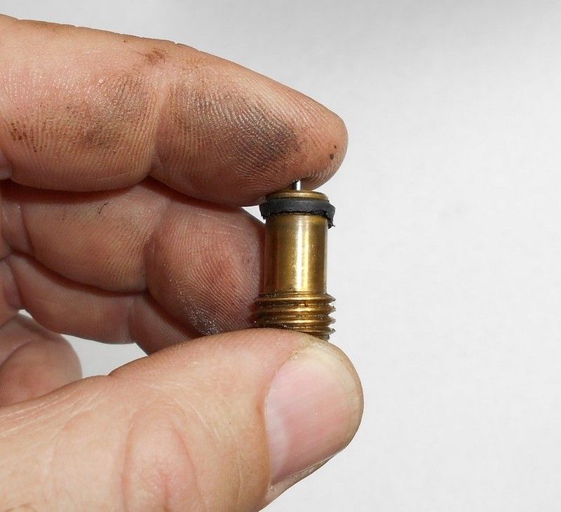
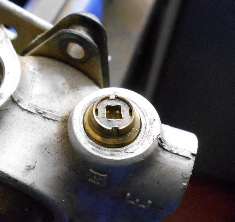
If you look inside hole A and E, you will notice brass locking screws that secure the one-way valves in place and prevent them from screwing in or out. These locking screws are removed by turning them out with a flat screw driver.
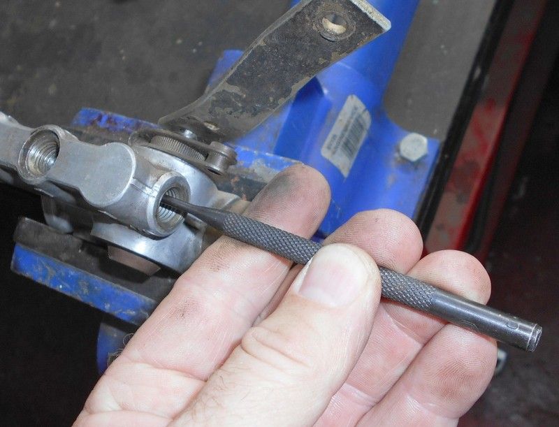
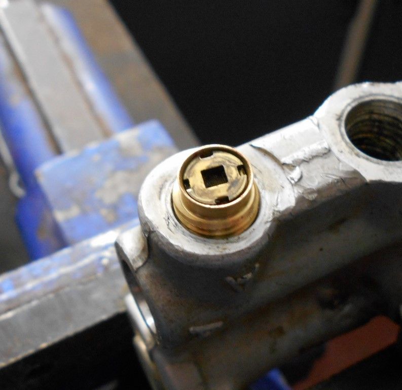
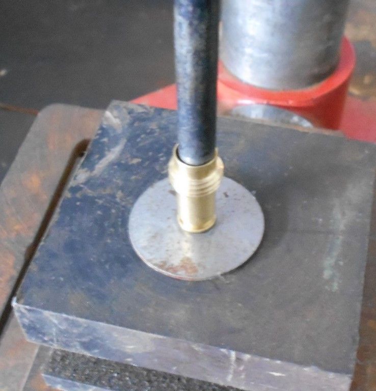
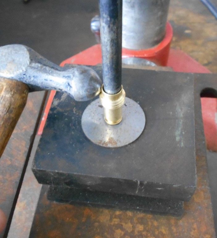
You will then see a small square hole on the top of the one way valve, and this is turned out with the second special tool that must be made, as below. It’s a screw driver with the end cut off, and then a square made at the end on a bench grinder – the square should be 3 x 3mm.
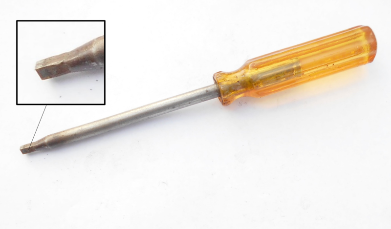
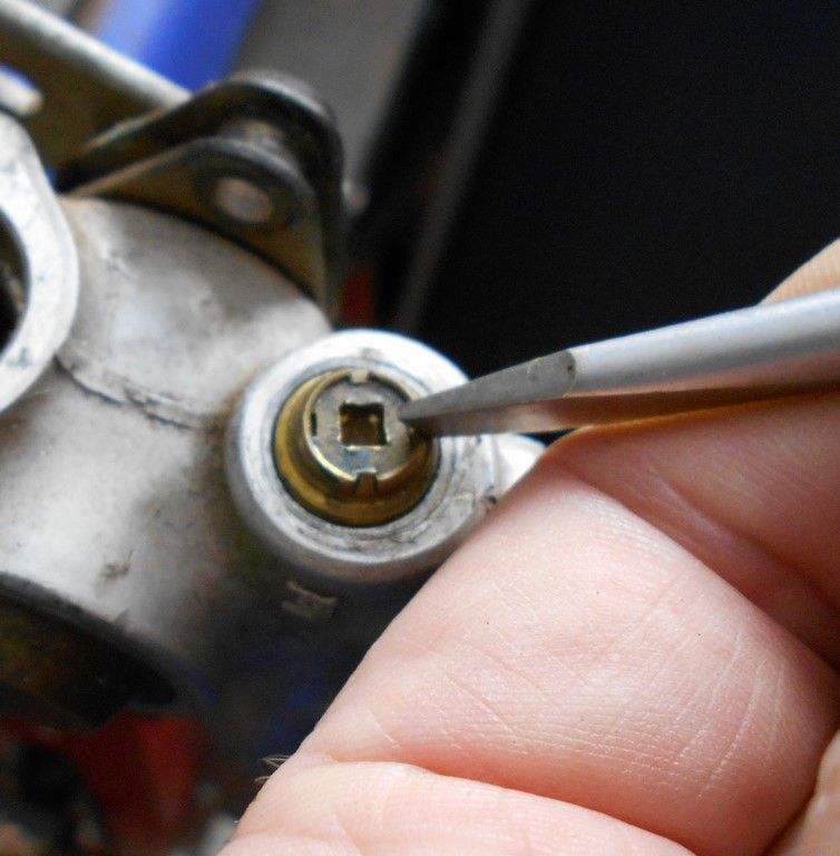
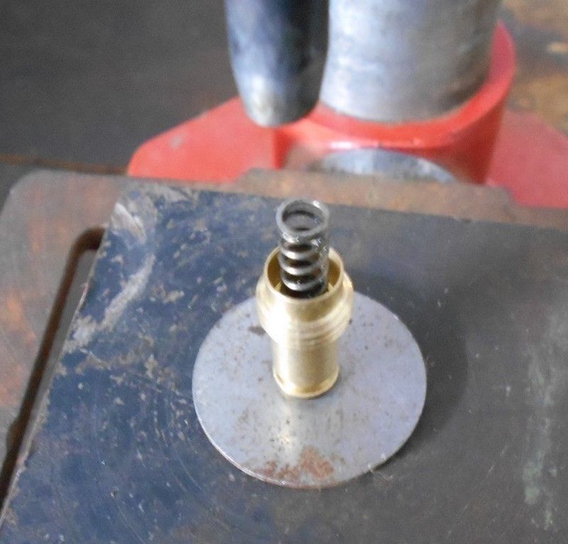
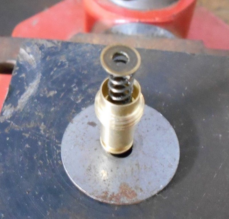
Insert the tool into the square on the one way valve and gently turn it out. If there’s resistance, keep a constant pressure and allow the valve to ease out. The square hole is in a washer at the top of the valve that is crimped in place, and there is a possibility that the crimping breaks and the washer turns within the housing if the valve is turned with a quick force. This is a problem and is not what you want, but it can be overcome. It means the valve must be drilled out, but I’ll cover this later. Sometimes the valves turn out without any resistance whatsoever – it all depends on the luck of the draw.
The two valves look the same, but you can differentiate between the two by pushing on the pin on the one-way valve. The activation pin on the exhaust valve A is much harder to push in compared to the pin on the inlet valve E.
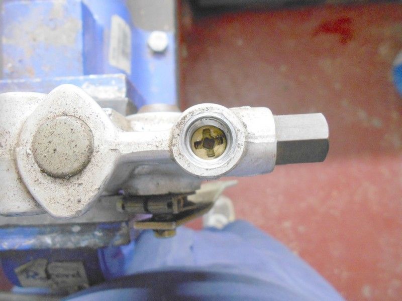
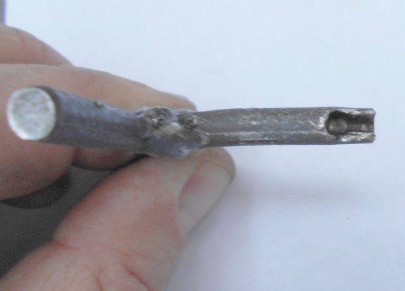
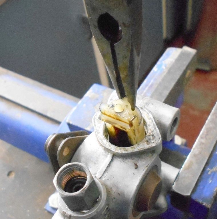
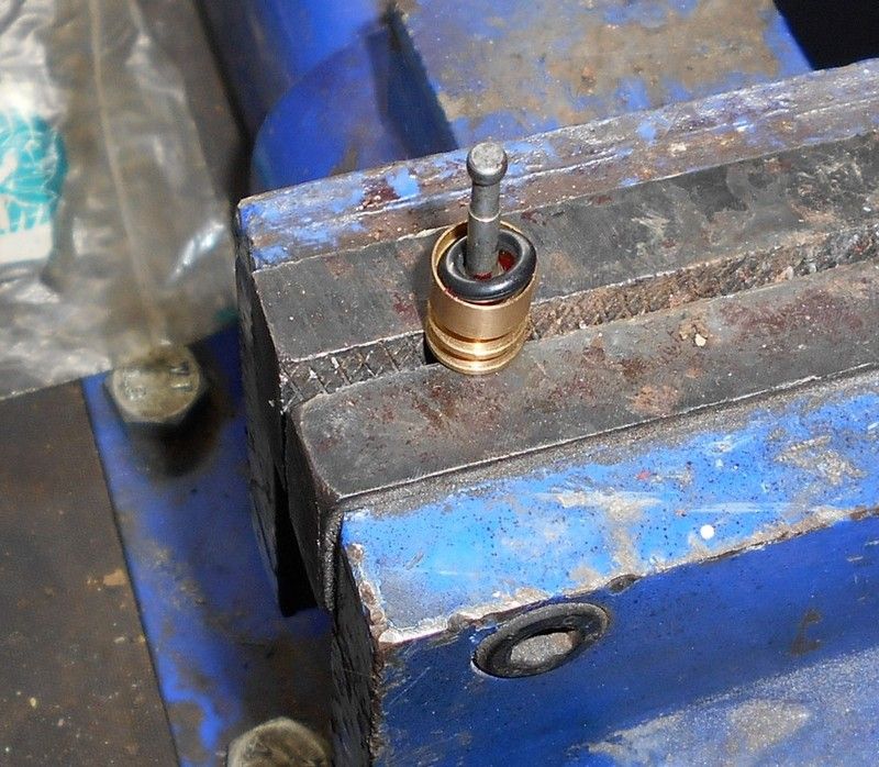
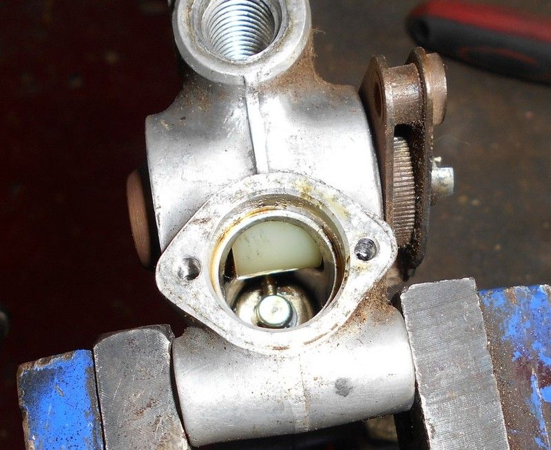
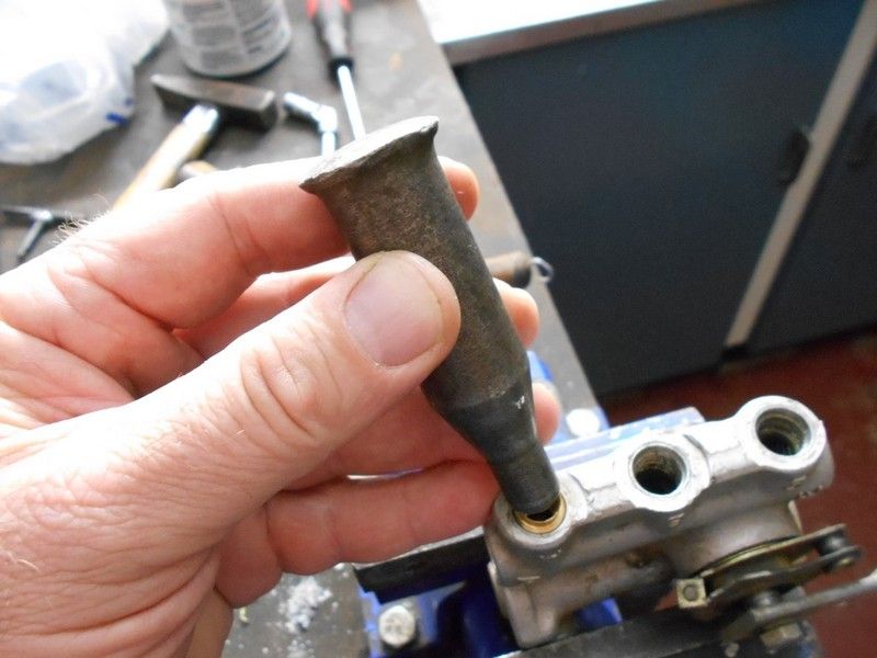
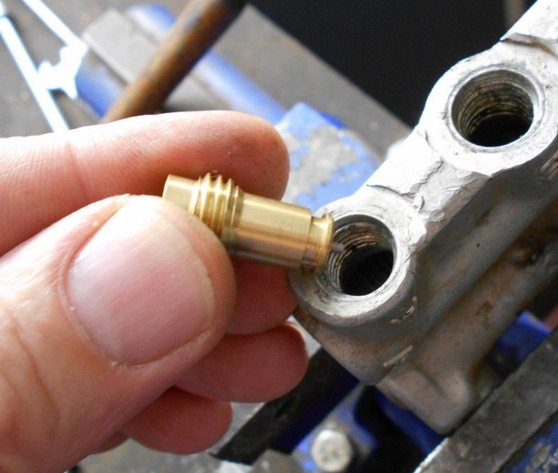
Once the valves have been removed, the brass sleeve through which the slide piston connected to the pivot pin needs to be removed. If you look down the B hole, you will see the brass sleeve with a hole in it, and as you move the lever of the air control arm, you will notice the slide piston on the end of the pivot pin sliding back and forth.
The sleeve is inserted from the one side and there is a slot in it to allow it to move past the pivot pin. The picture below shows how the pivot pin fits into the slide piston, which moves within the brass sleeve.
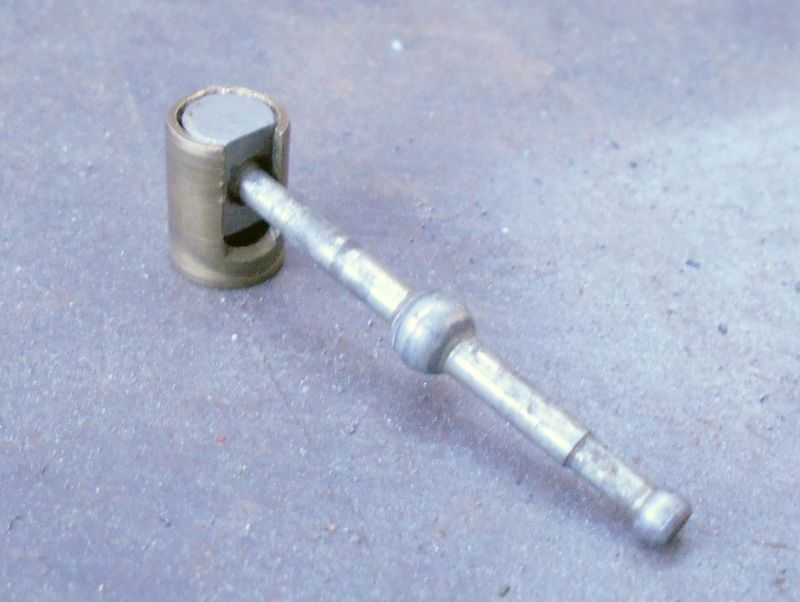
By looking down hole A or E, you can see which side is the slot side.
From the side which has the slot in the brass sleeve, use a thin flat-headed punch and gently tap the sleeve free. You may have to move the slide piston by means of the lever on the air control valve so that the brass sleeve does not wedge against the piston
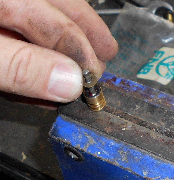
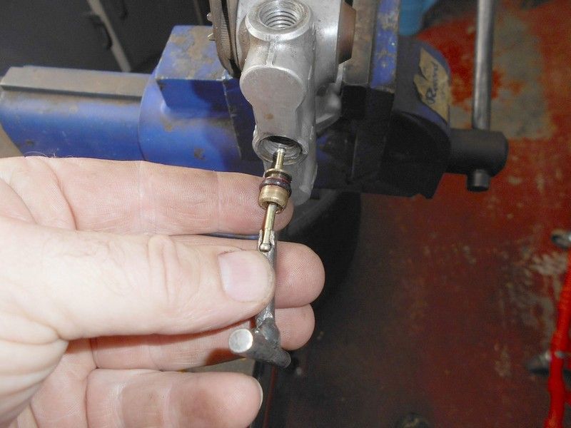
Remove the air control valve from the vice and while wiggling the pivot pin with the lever, turn the air control valve over into your hand, and the slide piston should fall out of hole B into your hand.
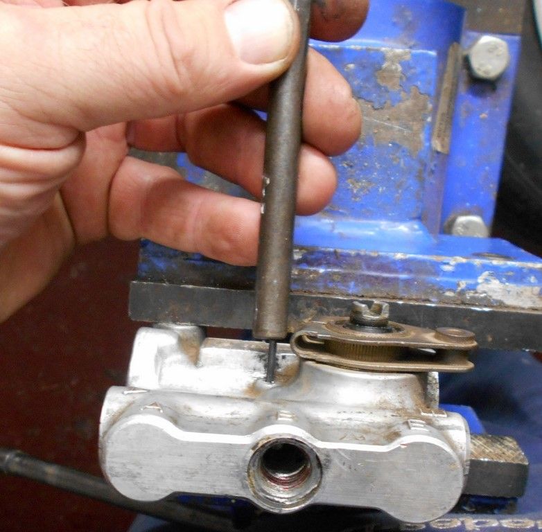
Now place the air control back in the vice as previously, and with a thin punch, knock out the spring pin that locates the pivot pin assembly.
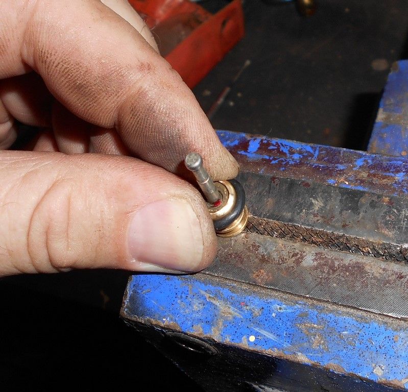
To pull out the pivot pin, the last special tool has to be made. This is a T-piece made from 6mm round bar, where the one end has a slot cut into it to accommodate the pivot pin.
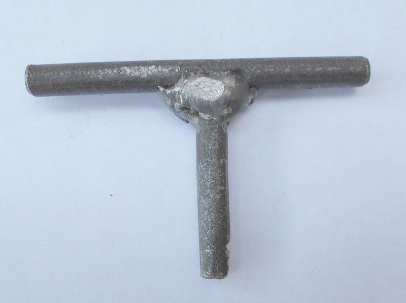
To make the tool, cut two lengths of 6mm round bar: 60mm for the handle and 35mm for the shaft. Take the shaft, and then mark it 6mm from the end. Drill a 3.5mm hole at this point that goes 2/3 of the way into the shaft. Then drill a 3 mm hole down the centre of the shaft until it meets the cross-drilled hole. Cut the side wall of the shaft out with a small hacksaw and file it so that the pivot pin fits into it.
Fit the tool onto the pivot pin and secure the handle of the tool into a vice so that the air control valve is against the vice. Use a flat screwdriver and lever the air control valve away from the vice and the pivot pin assembly will come out.
Next, the higher level piston and cylinder need to be removed. Place the control valve in the vice and remove the one screw. Keep the higher level cylinder in place with your thumb to ensure that the internal spring doesn’t launch it, and remove the other screw.
Gently ease the pressure on the higher level cylinder so that it safely comes away in one piece. Note the spacer washers on the thin shaft of the higher level piston. Sometimes these washers remain behind on the plastic rack, so ensure they are not lost.
Remove the gasket from the higher level cylinder and the spacer washers from the pin on the piston.
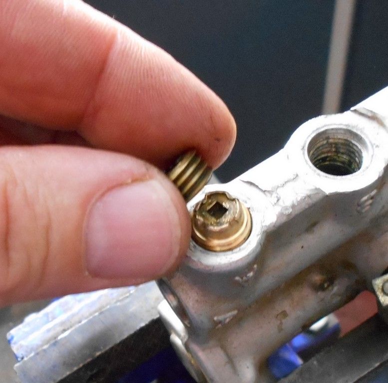
Remove the spring and washer and then remove the plastic rack with long nosed pliers. Put all these components aside in a tub for later assembly.
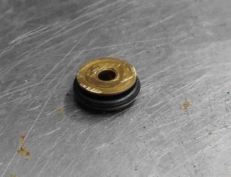
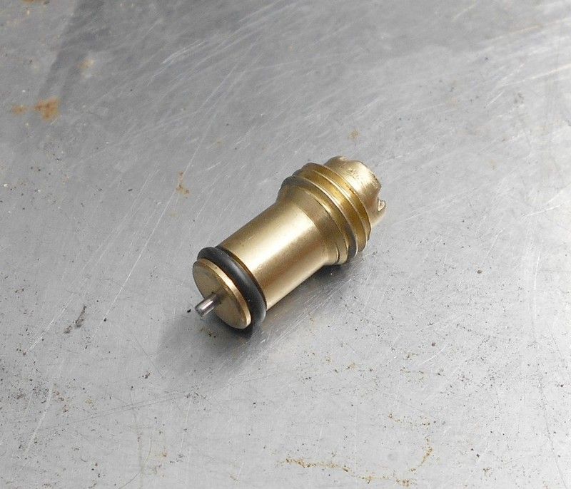
 Overhauling the Pivot Pin Assembly
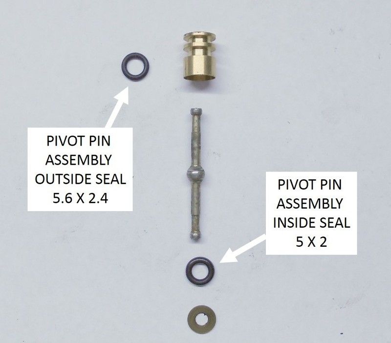
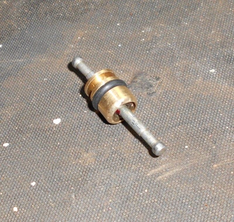
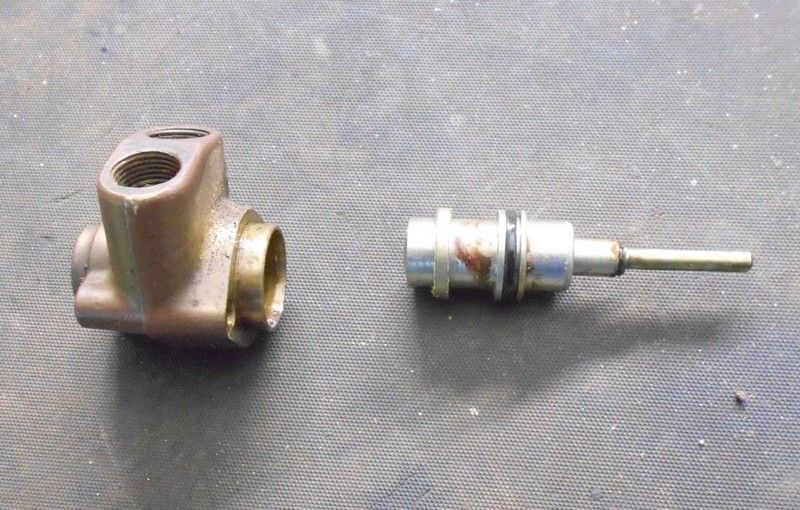
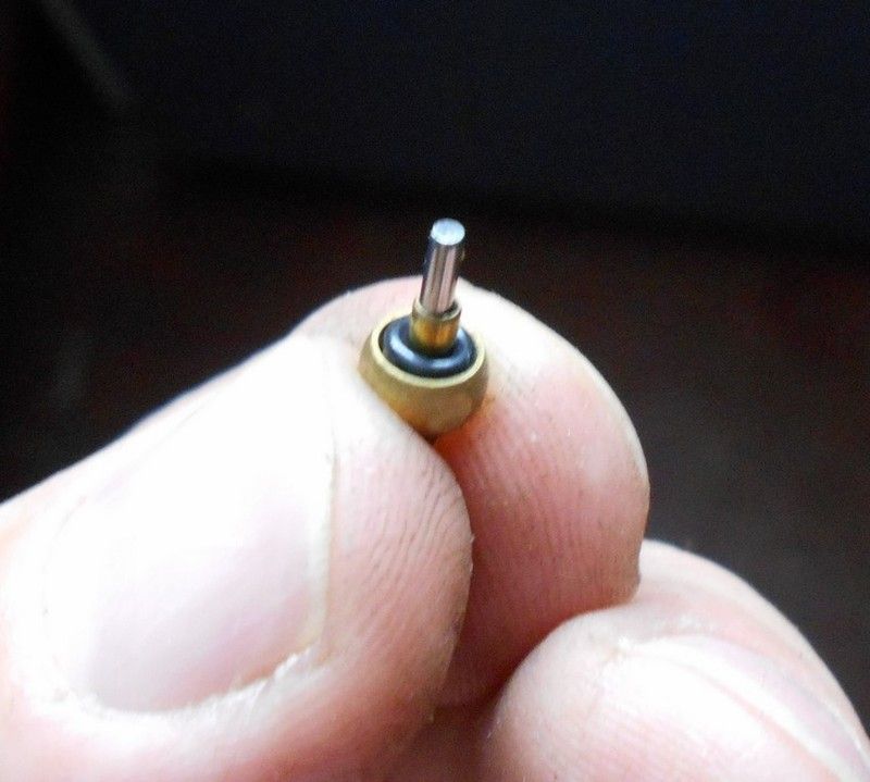
The pivot pin assembly consists of the following components: The pivot pin is inserted into the brass housing and then has a seal inserted. The seal is covered by a washer and then the brass housing is crimped over to secure everything in place.
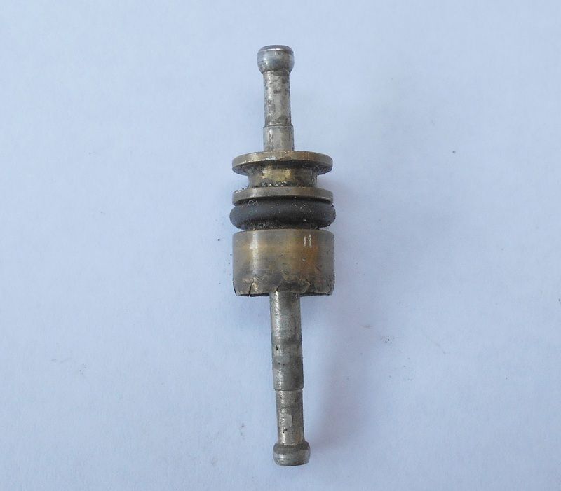
To disassemble the pivot pin assembly, the housing has to be un-crimped. It takes some patience, but it can be done and the housing can be re-used. However, the brass housing tends to be brittle with age, and as you try and un-crimp it, pieces can break out. I had an engineer turn me a few new housings in brass on his CNC lathe, using the old housing as a measurement reference. The steel pivot and washer will be re-used whether you’re using a new housing or able to save the old one.
Lubricate the ball of the pivot pin with a small dab of rubber grease, and insert it in the housing. Clamp the pivot pin lightly in the vice, insert the seal (5x2) and the washer.
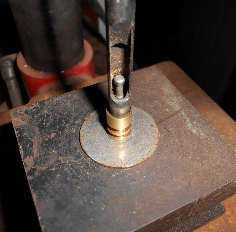
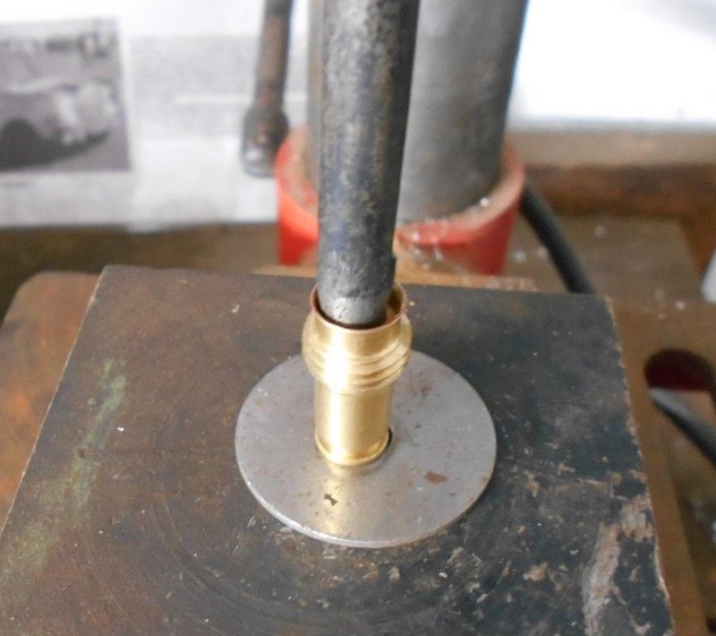
The washer and seal need to be compressed so that the housing assembly can be sealed. This is done in a drill press using a 6mm hole punch and a base with a hole in it that will keep the housing flat, but allow the pivot to go through it.
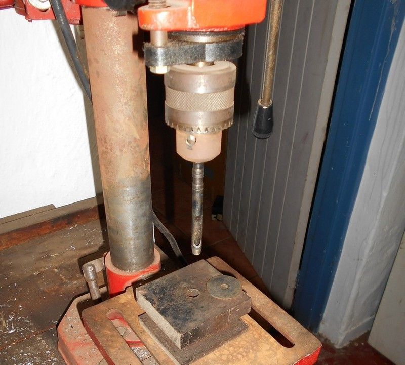
Put the pivot pin assembly into the hole in the base of the drill press, centre it and then gently compress the washer and seal. You will feel the seal give as it’s compressed and then stops when the washer bottoms against the ball of the pivot pin.
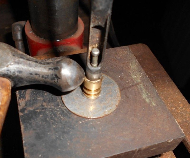
The edges of the housing can then be rolled over with a small ballpeen hammer to secure the washer and seal in place, which is then removed from the drill press and then completed in the vice.
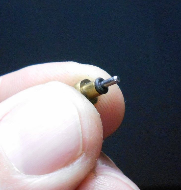
Fit the outside pivot pin assembly seal (5.6x2.4) and the pivot pin assembly is now ready to be re-fitted.
 Refitting the Pivot Pin Assembly
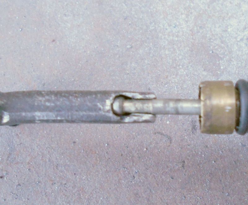
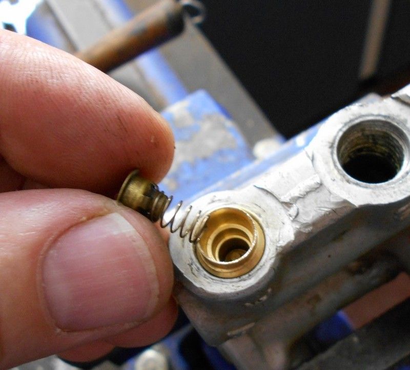
When re-fitting the Pivot Pin Assembly, note that the round head of the pin has to fit into the hole on the Spring Pin, as in the picture below.
Put a little rubber grease around the outer seal and insert the Pivot Pin Assembly into the Air Control Valve.
You will have to push the spring down with a screwdriver while inserting the pivot pin assembly. It will probably help if you had an extra set of hands while doing this, or come up with some special device, but behind the scenes – and don’t laugh - I just push down on the spring and hold it in place with my chin while the Pivot Pin Assembly is knocked into place.
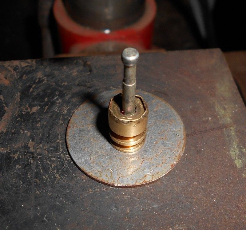
You will have to wiggle the pivot pin into the hole with the special tool and then you will feel it resist against the seal. You will then have to hit the handle of the special tool to force the Pivot Pin Assembly further into the hole and you will notice the round head of the Pivot Pin start to protrude. Align the hole in the Spring Pin with the round head of the Pivot Pin and tap the Pivot Pin Assembly home:
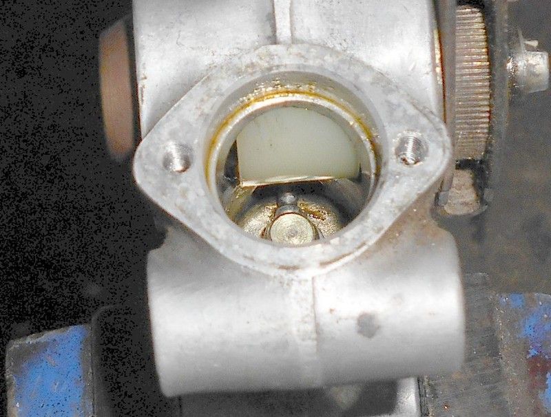
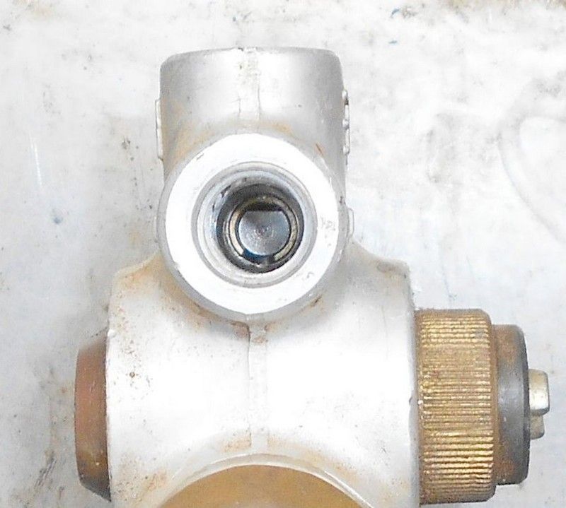
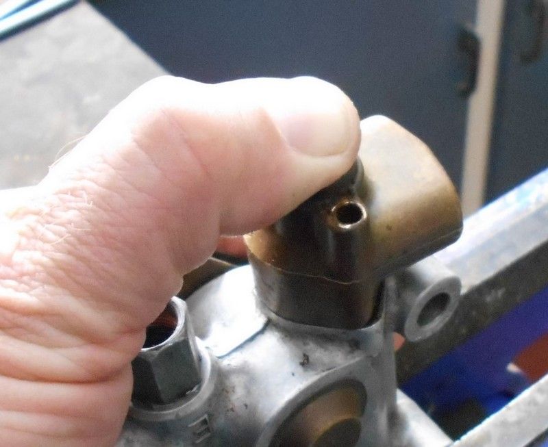
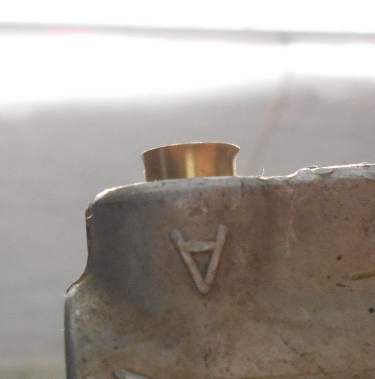
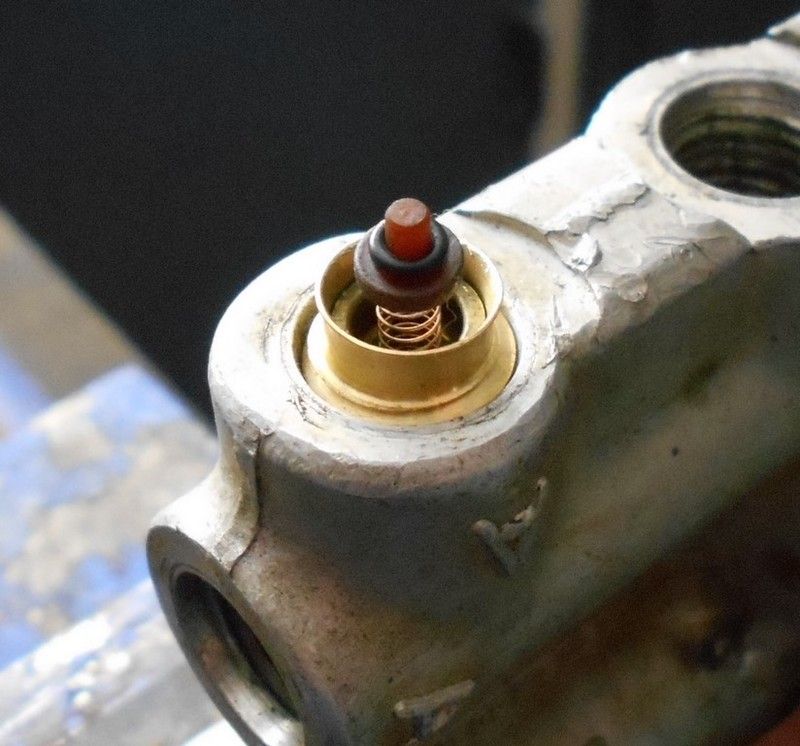
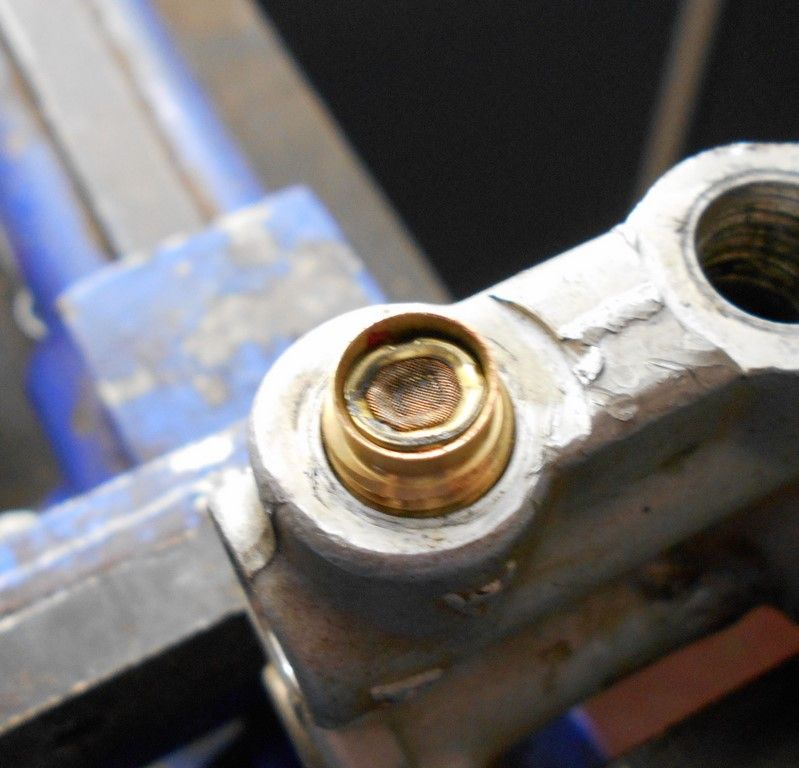
To ascertain where ‘home’ is, look down the hole for the inlet valves and the round head of the Pivot Pin should be evenly spaced in the centre of the hole:
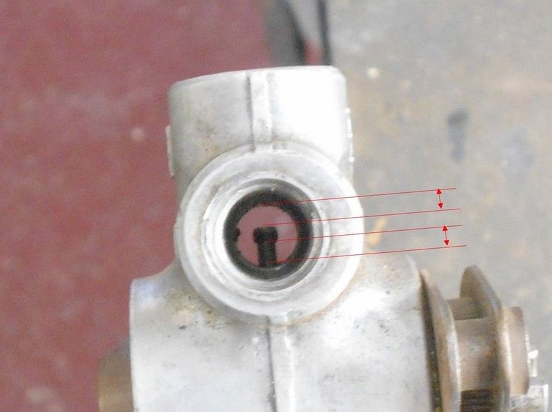
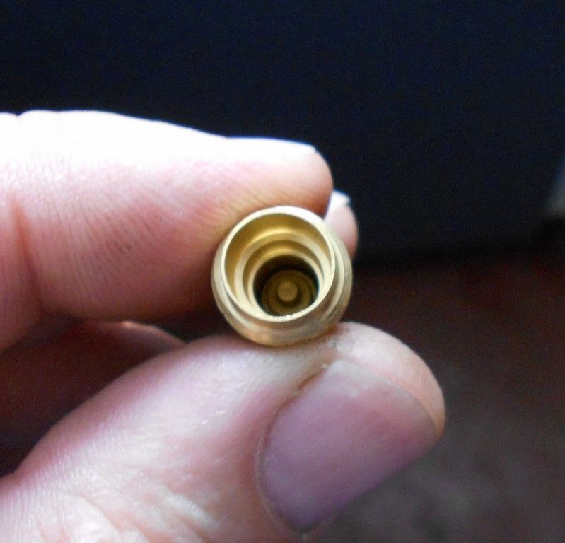
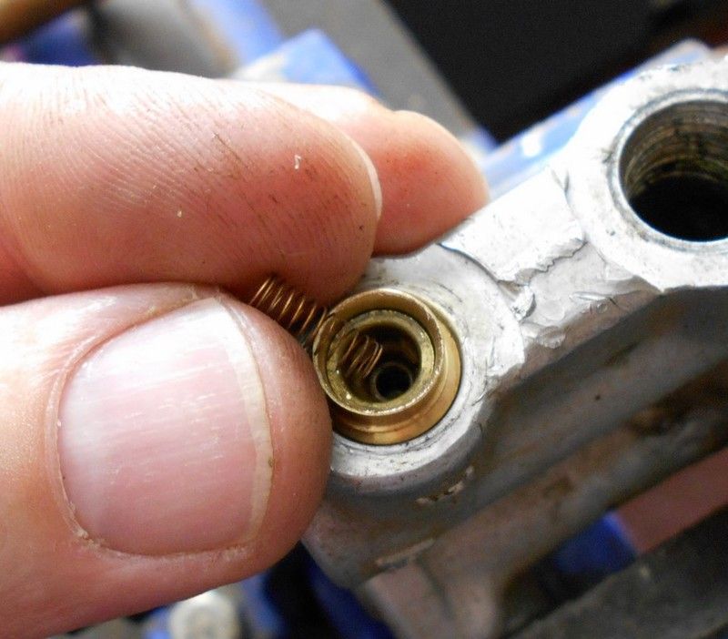
If you look through the small hole in the body of the Air Control Valve into which the Spring Pin locates the Pivot Pin Assembly in place, the hole should be clear. You can then insert the Spring Pin and tap it in place with a hammer and punch.
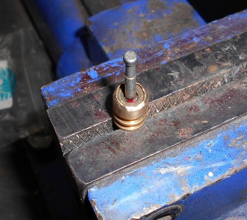
Block the holes ‘A’ and ‘E’ with stoppers and new seals, and then placed the air control valve under pressure by inserting the test gauge into connector ‘B’ – this must also have news seals between the valve body and connector, as well as inside the connector. The valve should hold pressure, which shows that the Pivot Pin Assembly is air tight. If there are any leaks, the gauge will drop within seconds.
 Refitting the Higher Level Cylinder and Piston
Clean the removed components and then fit a new O-ring seal (R2056) to the higher level piston. Give the O-ring seal a coating of rubber grease and insert it back into the cylinder, moving it back and forth to ensure that it moves freely. Insert the spacer washers back onto the pin of the higher level piston with some multi-purpose grease to keep them all together. Lubricate the pin of the higher level pin with some new grease.
Put some grease on the outside of the rack and push it back into place. Move the lever around so that the rack engages with slot on the pinion. Replace the spring and washer, place the gasket on the higher level cylinder and replace the unit, holding it down with your thumb while tightening the screws.
Refit the slide piston and brass sleeve with a touch of grease and check that it moves easily back and forth2. It must not stick at any point – the spring action should always allow the slide piston to return to the one side.
Once the slide piston and brass sleeve are back in place, it’s time to tackle the inlet and exhaust one-way valves. In my experience, it is often the case that these valves are still air tight and function properly by merely renewing the outside seals and it worth trying this first instead of having to strip and re-assemble the valves.
Renew the outside seals on the one-way valves with new O-ring seals (7.1x1.6). The seals need to be lubricated with rubber grease so that they turn comfortably on the valve. The valves are only crimped twice, but you should crimp the extra places so that the valve is crimped four times. The reason for this is that the new outer seals make turning the valves in very tight, which placed extra force on the two crimpings, possibly breaking them in the process. Not what you want.
Turn the valves into the relevant hole, crimp the additional places and then turn the valve into the housing. You will notice that the valve will feel like it stops turning, but this is when the new seal is starting to be compressed. At this point you need to take extra care to turn the valve with a consistent and even torque. You will eventually feel the valve ‘give’ and turn more easily and leave it be at this point.
Do the same with the other valve and then place the air control valve on test in the same way as above, by inserting the pressure gauge into connector B. Leave the stoppers off so that the air can escape if the valves are not air tight. If there is no movement on the gauge, then the one-way valves are air tight and you can go to the next step to do the final set up. If the gauge drops, one of the two valves, or both, are faulty and you can check this but putting the air control valve into a bucket of water and see from which hole the air escapes, indicating which valve is faulty.
I don’t know if these valves are still available from MB, but if they are, this is first prize. I have a part number for the exhaust valve: 1 507 413 039. I think this is a Bosch part number, not a MB part number.
I have had and CNC engineer turn new valve housings and internal components for me to be able to assemble the valves.
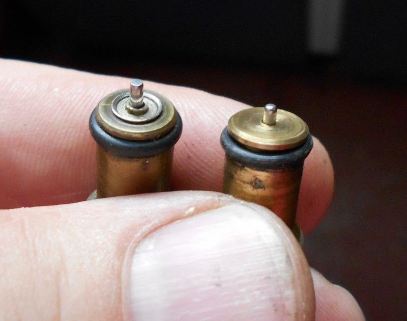
The Inlet and Exhaust One-way ValvesThere are two variants in these one-way valves in terms of their internal designs and workings. I don’t know if these two designs were used at the same time (maybe different suppliers?), or whether there was a change over at some point. The valves on my 1964 300SE W112 with the early, simple air control valves are those with the brass housing – could this have been an earlier design?
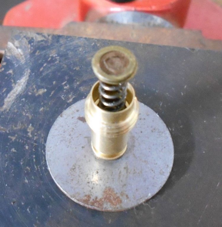
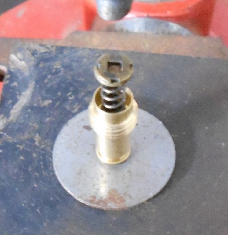
You can tell the two different designs externally by looking surface where the activating pin is - the one has a chromed insert and the other a normal flat finish. The valves with the chrome inserts seem to be the ones that fail the most. The valve with the flat finish is the one that I’m concentrating on, as it’s easiest to overhaul using standard O-ring seals.
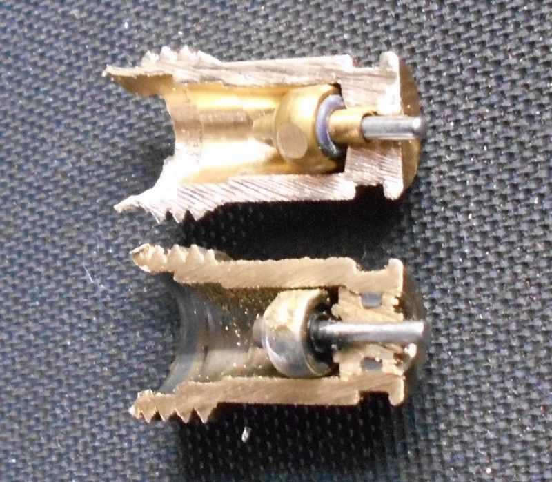
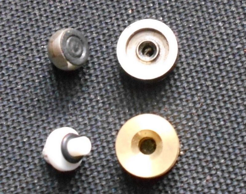
If you disassemble the two valves, you can clearly see the different ways that they seal:
- The valve with the chrome insert has a raised edge and the seal housing has a rubber seal cast into it, which seals when the housing pushes up against the raised edge
- The valve with the flat finish has an O-ring seal on the seal housing that pushes up against a flat surface.
 The Inlet Valve
This is a technical drawing of the inlet valve:
These are the different components:
When the inlet system builds up pressure, the piston (1) and its O-ring is pushed back by the air pressure and air enters the valve until the air pressure equalizes, when piston (1) is returned to its seating position by the spring. The pressurized air inside the valve cannot go anywhere because the outlet is sealed by piston (2) and its O-ring, which is held in place by a spring.
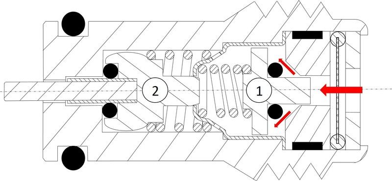
When the activating pin on piston (2) is pressed via the slide piston, the pressurized air inside the valve moves past the O-ring seal into the air control valve on its way to the bellow, while piston (1) is pushed back and more pressurized air moves into the system
The Inlet Valve fails in the following ways:
1) The O-ring seal (3) on the outside of the seal is faulty and allows air to escape around the one-way valve into the inlet system. This will only happen if the inlet system has a leak and the air pressure is lower on the inlet side. It is more likely that the pressurized air will bypass seal (3) and be exhausted by the exhaust valve until there is no more pressure in the inlet system. If seal (3) is hard, chances are that the seals in the pivot pin assembly are hard as well, so the whole valve will be leaking.
2) If the O-ring seal on piston (2) is hard, the air will escape past this seal, but be trapped inside the valve if the O-ring seal on piston (1) is still good.
3) If the O-ring seals on both piston (2) and piston (1) are faulty, the air will escape from the bellow into the inlet system, provided the pressure in the inlet system is less than that in the bellow.
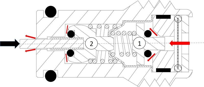
The Exhaust ValveThis is a technical drawing of the exhaust valve – it’s much simpler than the inlet valve:
These are the different components:
The spring is strong enough to overcome the air pressure in the bellow to keep piston (1) pushed in place against the O-ring seal and housing, sealing the exhaust valve. When the activating pin on piston (1) is pressed via the slide piston, the pressurized air inside the bellow moves past the O-ring seal through the one-way valve into the exhaust system.
The Exhaust Valve fails in the following ways:
1) The O-ring seal (2) on the outside of the seal is faulty and allows air to escape around the one-way valve into the exhaust system. This is a common failure.
2) If the O-ring seal on piston (1) is faulty, the pressurized air in the bellow will escape past this seal into the exhaust system.
3) If the spring has become weak, the air pressure in the bellow will push piston (1) back and the air will escape through the exhaust valve. Not a common problem
Overhauling the Inlet ValveEnsure that your working environment is clean and as dust free as possible.
Using the air valve as a jig, screw in the inlet valve housing a thread or two. Flare the edges of the valve with a round punch and hammer – this will help when inserting the sealing washer.
Insert a new O-ring seal (2x1) over the activating pin/ piston assembly and insert this into the inlet valve. Ensure that the activation pin is protruding from the valve.
Insert the short spring and the spring locator
Insert the long spring
Fit a new O-ring seal (2x1) onto the second piston and place this on top of the spring.
Fit a new O-ring seal (6 x 1.5) onto the sealing washer and give it a light coat of rubber grease.
Place the sealing washer with the conical side on the piston and seal and push this down till it comes into contact with the valve housing. Holding the assembly together, remove the valve from the jig and place it under the hole punch in the drill press, and then press the sealing washer gently into the valve housing until it stops in place.
Remove the valve from the drill press and screw it back into the jig. Insert the filter gauze.
IMG]http://i67.photobucket.com/albums/h305/aquariusg/Air%20Suspension/Rebuilding%20Inlet%20Valve/DSCN3298-1%20Copy.jpg[/IMG]
Insert the locking plate and crimp it into place with a flat screw driver. Peen the edges over the locking plate.
Fit the locking screw over the inlet valve to check that it fits properly. If not, file some of the edges so that the locking screw fits over the valve and turns without sticking. If this is not done, the locking screw may turn the valve when doing the final set-up instead of locking it into place.
Note that if any filing is done, ensure that no filings get into the valve.
Fit a new seal (7.1 x 1.6) to the outside of the seal. Press the activating pin a few times to ensure that it moves freely – there should be no sticky movement.
 Overhauling the Exhaust Valve
Overhauling the Exhaust valve is done in much the same manner as the Inlet valve, except that it’s much simpler.
Insert a new seal into the activation pin of the piston and insert this into the exhaust valve housing.
Place the valve housing and piston in a drill press and insert the spring.
Place the locating washer on top of the spring with the plush side up – make sure that the washer located in the spring.
Place the filter gauze on top of the locating washer.
Place the locking plate on top of the filter gauze.
Hold the washer, gauze and locking plate between your fingers to guide them into the housing when you press the assembly into place.
While holding the assembly together, peen the edges of the valve housing over the locking plate. When complete, remove the exhaust valve from the drill press and complete the crimping in the jig.
Fit the locking screw to check fitment, as with the inlet valve. Fit a new outer seal (7.1 x 1.6).
Calibrating the Valves - Exhaust ValveThe outside seal needs to be lubricated with rubber grease so that it turns comfortably on the valve. Turn the exhaust valve into hole ‘A’ until it feels like it stops turning. This is when the new seal is starting to be compressed and at this point you need to take extra care to turn the valve with a consistent and even torque. You will eventually feel the valve ‘give’ and turn more easily until it stops against the slide piston. It is now in the open position.
Connect the test gauge into Connector ‘B’ and insert a 4mm pin into the lever – the lever is now in the neutral position.
Connect the test gauge onto a compressor line and open the test gauge valve. Compressed air will flow through the exhaust valve and exit hole ‘A’, i.e. air will flow from the below through the exhaust valve. Shut off the valve on the test gauge and turn the exhaust valve out a full turn. Open the valve on the test gauge and see if air is still being exhausted. If so, shut of the test gauge valve off and turn the exhaust valve out some more. Open the test gauge valve again. Keep doing this until no more air is exhausted out of hole ‘A’.
Take the 4mm pin out of the lever and check at what point the exhaust valve starts to work in relation to the lever and the neutral hole. Adjust the exhaust valve in or out so that the lever is about 1mm into the neutral hole when the exhaust valve opens. When the 4mm pin is inserted, the exhaust valve stops working. At this point, the locking screw can be installed to lock the exhaust valve in place.
The same procedure is followed to set up the Inlet valve, except that the test gauge is connected into hole ‘E’ and the air exits hole ‘B’, i.e. compressed air flows through the inlet valve into the bellow. The relation between the lever and the hole is the same 1mm, where if the 4mm pin is inserted, the inlet valve stops.
Once the calibration has been done, fit new O-ring seals to all the connectors (9 x 2) and re-fit them onto the control valve. Renew all the seals inside the connectors (7 x 2) and on the higher level cylinder.
To check that the higher level piston is working, screw the test gauge to the hole on the cylinder and block off the other hole if it doesn’t already have a stopper already in place. Keep the test gauge valve open, and connect the test gauge to a compressor line – the lever on the valve should move. When you disconnect the compressor line from the test gauge, the lever will return to the normal position.
With the 4mm pin inserted into the neutral position, connect the test gauge to connector ‘B’. Connect the test gauge to the compressor line and then open the test gauge valve till the air control valve is under pressure. Shut off the valve on the test gauge and note the pressure reading on the dial. If the control valve is not holding pressure, the dial will show a loss of pressure within minutes. If it’s holding pressure, check the dial twenty four hours later and the pressure should be the same.