| Last Post |

6.3Nut
|
|
9/12/2019 11:13 PM

|
I finally did it - Used turn buckle to pull the bands into place.
|
|
|
|
6.3Nut
|
|
9/9/2019 8:35 PM

|
Thanks for the info. will try it. These new rubbers are taking a lot of force to stretch. I was almost applying close to 40 to 45 lbs of force. The string was more like a small tent rope, looped around the engine shock for tangential Force. I was going to do that on the driver side but the compressor pulley is in the way.
|
|
|
|
cth350
|
|
9/9/2019 7:36 PM
|
|
been a while, but back in the prior century, I would put them on the radiator, put it in place and then with a long pry bar, hook them in place. I recall it being the prybar through the donut, loop it around the body hook and then it would pop in place.
Given that lever action, I'm not sure just how much force I put into it. I'd say probably more than what a string would be capable of.
-CTH
|
|
|
|
6.3Nut
|
|
9/7/2019 9:13 PM
|
Guys need a bit of help. I am installing the radiator, sliding it in is easy, it is the rubber rings that are causing heart ache. Can someone tell me what are the correct steps to hook the rubber rings, does the ring first need to be installed on the radiator and once the radiator is pushed all the way in, the ring is pulled and hooked onto the hook on the body or does the ring need to be first put on the hook on the body and then pulled onto the radiator before it is pushed down. Also, how much Force is required to pull the rings, the ones I received from Tom really take a lot of force, I have to pull them using a sting and then plop them on the hook.
|
|
|
|
6.3Nut
|
|
1/21/2018 1:36 PM
|
|
Art apologies are in order. I was mistaken about that line. This, as usual, shows your immense knowledge.
There cars and then there are BABIES!
1969 Euro Model
10901812000931
|
|
|
|

paul-NL
|
|
1/20/2018 7:03 AM
|
|
Thanks Anthony and Art,
Learned again something new.
Sorry for my confusion in this matter.
|
|
|
|
Art Love
|
|
1/20/2018 1:31 AM
|
This is silly. I've provided photographs of the high pressure oil line to the MFI in both the 600 and the 6.3 motors plus the part numbers and descriptions of this oil line and I am being told that this oil line does not exist or it is an after market modification. This is a one way pressure line that pressurizes the injector elements in the MFI. There is no through flow. The fuel inflow and outflow lines on the MFI are visible in a couple of the photos I posted at the front at the top on the left and to the rear at the top on the left. As Ant correctly pointed out and as I have shown in my photos, the oil inflow port on the MFI is on the right side of the pump part way down below the 6th injector element, on the opposite side of the pump from that shown in the 6 cylinder pump that Paul posted a photo of. 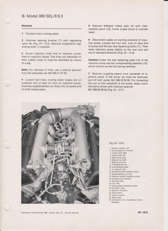 Here is the page from the Service Manual describing removal of the MFI in the 6.3. Note paragraph 4. 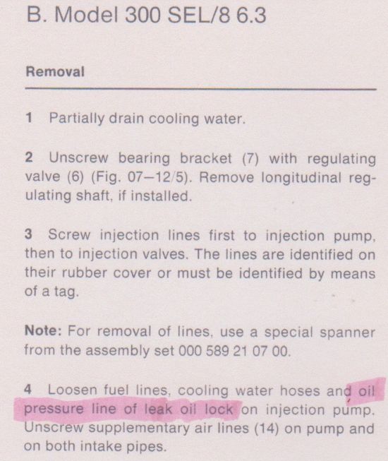 Here is the relevant reference highlighted in paragraph 4. 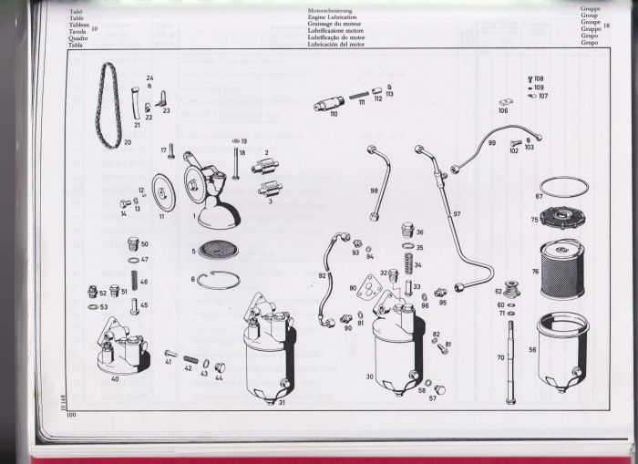 Here is the relevant page in the M100 Parts Manual showing the oil system for the motor. 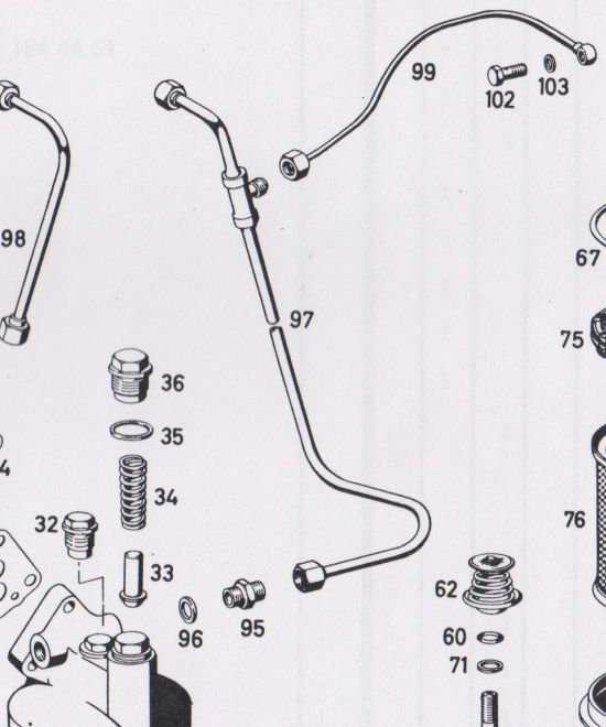 Here is the part of the page showing the set up in the early 600. Part 97 is the oil pressure line to the fan coupling shut off valve. Part 99 is the oil pressure line from that line via a T junction to the MFI where the banjo fitting and hollow bolt are shown. In the 6.3, the fan has a viscous coupling, totally different from the oil fed fan clutch on the 600 and pipe 99 goes all the way from the oil filter housing. This is not shown in the Parts Manual. 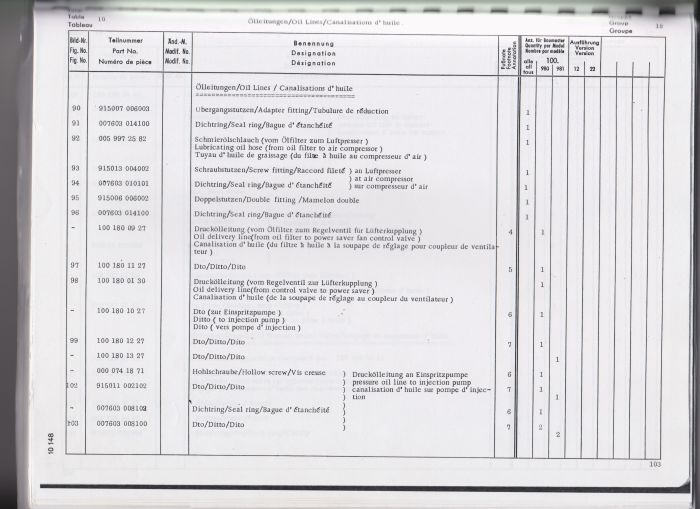 Here is the page with the description of the parts shown in the diagram page. 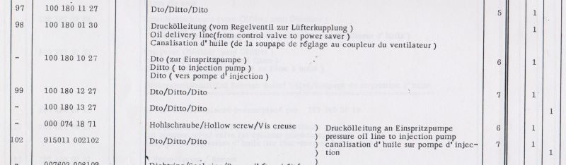 Here is the description of part 99 clearly stating that it goes to the injection pump. These are the part numbers that I described earlier today. This is NOT an after market modification. This oil pressure line is in all 6.3's and 600's. As I said, it has nothing to do with the MFI lubrication, totally unlike the 6 cylinder pump that Paul illustrated. As far as I understand it, the oil pressure that it provides acts as a seal against fuel pressure in the injector elements. Sorry to have to repeat myself. Art
|
|
|
|

abl567
|
|
1/20/2018 12:05 AM
|
|
Here's a thread on the subject.
http://m-100.co/forum/topic.asp?TOPIC_ID=4611&SearchTerms=MFIP,oil,line
300SEL
6.3 #2723, my first classic Benz
3.5 #8659, my second.
2 to go...
|
|
|
|
abl567
|
|
1/19/2018 11:54 PM
|
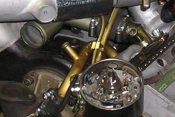
Here is the oil inlet, centre of frame 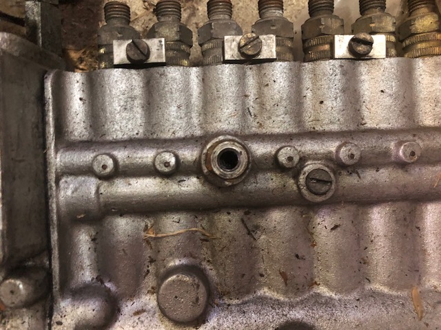 300SEL 6.3 #2723, my first classic Benz 3.5 #8659, my second. 2 to go...
|
|
|
|
abl567
|
|
1/19/2018 11:52 PM
|
Inlet and banjo fitting 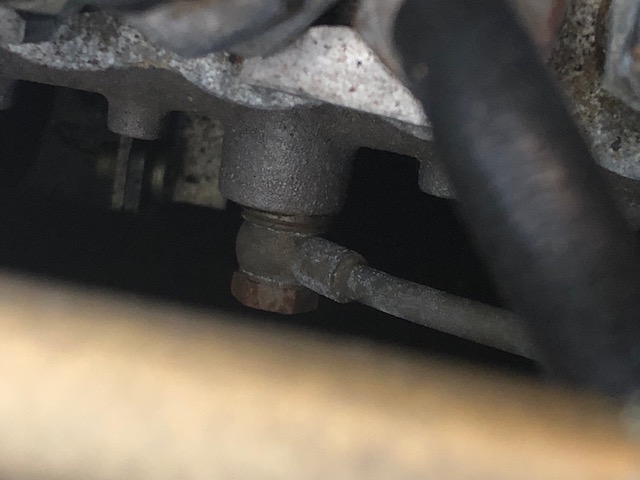 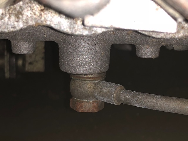 300SEL 6.3 #2723, my first classic Benz 3.5 #8659, my second. 2 to go...
|
|
|
|
abl567
|
|
1/19/2018 11:42 PM
|
|
That is a 6 cyl pump, the oil feed is on the other side opposite the bosch tag on a 6.3 8 cyl pump. I've removed and refitted it more times that I care to remember.
Pics to follow.
300SEL
6.3 #2723, my first classic Benz
3.5 #8659, my second.
2 to go...
|
|
|
|
6.3Nut
|
|
1/19/2018 11:08 PM
|
quote:
Originally posted by paul-NL
Art,
there is no OIL-line connected to the FIP for the 6.3 ltr motor, but only a fuelinlet and fuelreturnline
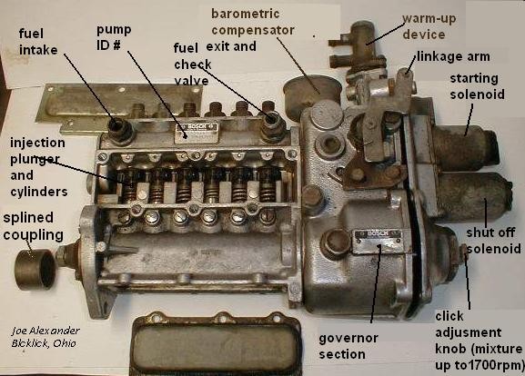
If my memory serves me right, as per Hanns the gentleman who build these pumps on Long Island ,NY, some people have modified pumps installed in their cars. He did not like it since it causes fuel to enter motor oil if the pump starts leaking. Any who, Art the pump on my 6.3 is exactly as per the image posted by Paul. There cars and then there are BABIES! 1969 Euro Model 10901812000931
|
|
|
|
paul-NL
|
|
1/19/2018 10:07 PM
|
Art, there is no OIL-line connected to the FIP for the 6.3 ltr motor, but only a fuelinlet and fuelreturnline
|
|
|
|
Art Love
|
|
1/19/2018 8:08 PM
|
Here are some photos. 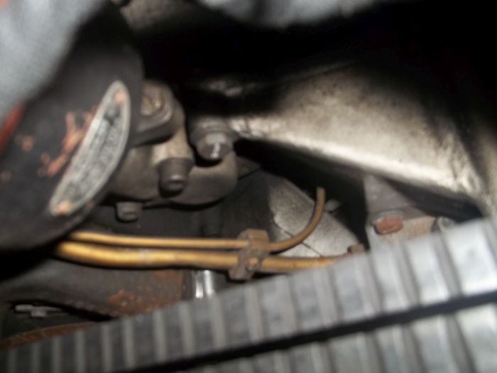 shows the small calibre high pressure oil line coming forward from the oil filter housing to join the fuel line on #765. 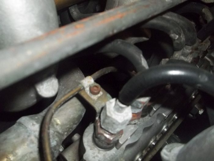 shows the same line where it is attached by a bracket to the first injector line on the MFI on #765. The photo you have already copied shows it at the front of the motor. 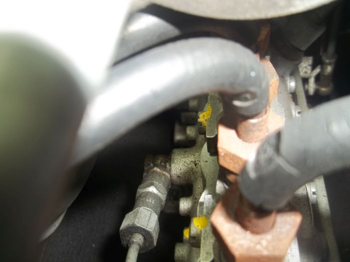 Here is the line attached to the right side of the MFI on #765 via a banjo fitting. Whoops, wrong photo - this is the banjo fitting on the 600. I'll add the photo of the fitting on #765 at the bottom. Now for Paul, here is the set up on 600 #178. It should be the same on his 600, but his will have the supplementary oil filter in the high pressure oil line to the fan clutch thermostat shut off valve, so the piping from the oil filter to the valve may be slightly different. 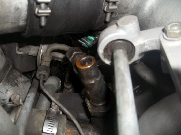 This shows the T junction for the small calibre high pressure oil line to the MFI from the high pressure oil line to the fan clutch valve which is to the right. 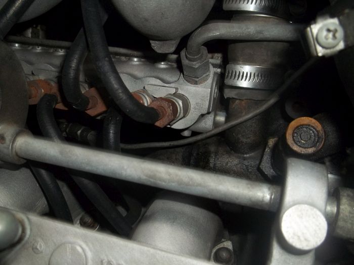 This shows the line in the 600 with the T junction to the right and the banjo fitting on the MFI on the left. The 600 banjo fitting on the right side of the MFI is shown above - see my correction. Here is the fitting on 6.3 #765. 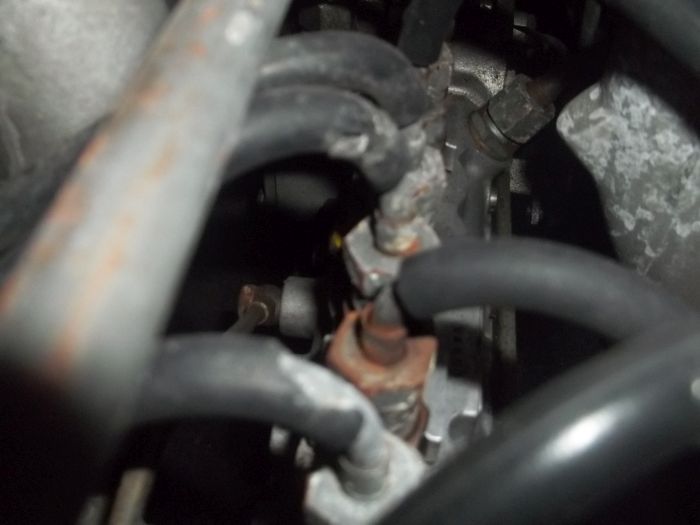 Art
|
|
|
|
Art Love
|
|
1/19/2018 7:11 PM
|
|
I am loath to and very rarely disagree with my friend Paul, but on this occasion, he is incorrect. In the 600, this line is a "branch" from the high pressure oil line to the hydraulic fan clutch and in my #178, it feeds from the inflow line to the fan control thermostat valve to the right side of the body of the MFI where it is attached via a banjo fitting. In both my 6.3's, #765 and #1702, it feeds from the oil filter housing to the right side of the MFI where again it is attached via a banjo fitting. In both 6.3's, it hitches a ride on the fuel line to which it is attached by several of the clamps shown in the photo.
It is a narrow calibre line as shown and has nothing to do with lubrication of the MFI. My understanding is that it pressurizes the injector units against fuel pressure.
Its part number in 600's up to Motor 990 is 100 180 10 27 and from #991 is 100 180 12 27. In the 6.3 its part number is 100 180 13 27, the 180 indicating that it is an oil line and its description being Druckolleitung zur Einspritzpumpe or Oil delivery line to injection pump.
It should be there.
Art
|
|
|
|
6.3Nut
|
|
1/19/2018 2:08 PM
|
quote:
Originally posted by paul-NL
"That is the high pressure oil line from the oil filter housing to the MFI. It should be there"
Be aware the M100 FIP has NO oilline .... It has an oilfillcap and a dipstick to checking the level ....
That is what I thought. So what is this high pressure line for or is this a modification? There cars and then there are BABIES! 1969 Euro Model 10901812000931
|
|
|
|
paul-NL
|
|
1/19/2018 12:54 PM
|
|
"That is the high pressure oil line from the oil filter housing to the MFI. It should be there"
Be aware the M100 FIP has NO oilline .... It has an oilfillcap and a dipstick to checking the level ....
|
|
|
|
6.3Nut
|
|
1/19/2018 12:38 PM
|
quote:
Originally posted by Art Love
That is the high pressure oil line from the oil filter housing to the MFI. It should be there. The hose clamps on the large diameter air hose should also be there. That photo was taken during rebuilding of that motor and the clamps were still to be applied.
Art
Thanks Art, I will check for the High Pressure line, since it is not taking the route as shown in your picture, it must be coming from the back. There cars and then there are BABIES! 1969 Euro Model 10901812000931
|
|
|
|
Art Love
|
|
1/18/2018 11:40 PM
|
|
That is the high pressure oil line from the oil filter housing to the MFI. It should be there. The hose clamps on the large diameter air hose should also be there. That photo was taken during rebuilding of that motor and the clamps were still to be applied.
Art
|
|
|
|
6.3Nut
|
|
1/18/2018 10:17 PM
|
quote:
Originally posted by Art Love
Something crazy has been done to those prices. They were not even a quarter of that price 3 years ago as best I recall. The picture I posted lacks detail at less than 80Kb, so I have been fiddling to get a cropped view. Here it is.
Art
Hey Art, what is that line, clamped to the fuel line coming from the sender? I do not have this in my car and have not noticed it in the few pictures I have seen. Also the hose on the left side intake manifold does not have clamps, is it suppose to be that way? The reason being I see them in my car and if they are not required then I will take them off. There cars and then there are BABIES! 1969 Euro Model 10901812000931
|
|
|
|